
Belt drive system

一种皮带传动、皮带的技术,应用在传动装置、皮带/链条/齿轮、带有齿的元件等方向,达到减少旋转力矩的降低、防止摆动和侧移、增强效果的效果

Inactive Publication Date: 2005-11-30
BANDO CHEM IND LTD
View PDF2 Cites 5 Cited by
  • Summary
  • Abstract
  • Description
  • Claims
  • Application Information

AI Technical Summary

Problems solved by technology

[0007] In addition, there is a known technique of placing guide rollers on both sides of the flat belt, thereby limiting the running position of the flat belt (see, for example, Japanese Unexamined Utility Model Publication No. 63-6520)

Method used


Image

  • Belt drive system
  • Belt drive system
  • Belt drive system

Examples


Embodiment Construction

[0052] Embodiments of the present invention will be described in detail below with reference to the accompanying drawings.

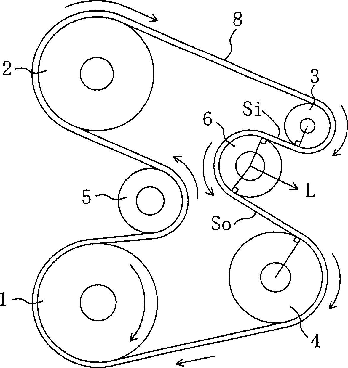
[0053] figure 1 An arrangement diagram of belts and pulleys in which the belt drive system according to the present invention is applied to an engine accessory drive system A is schematically shown. In this figure, reference numeral 1 denotes a crank pulley as a driving pulley mounted on a crankshaft (not shown) of the engine E for integral rotation therewith. Reference numerals 2-6 represent driven pulleys, which include a PS pump pulley 2 that is mounted on a rotating shaft of an accessory power steering pump (not shown) of the engine, and rotates integrally with the rotating shaft; an accessory AC mounted on the engine On the rotating shaft of the generator (not shown), the alternator pulley 3 rotates integrally with the rotating shaft; the air conditioning compressor (not shown) attached to the engine is installed on the rotating shaft, and the comp...


PUM


Abstract

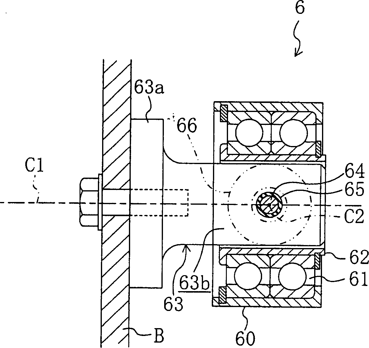
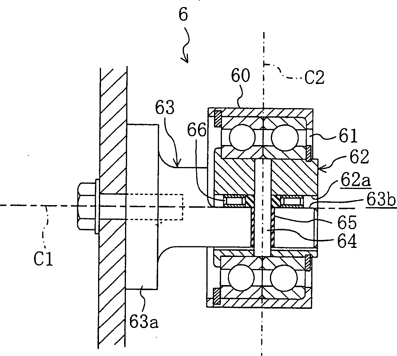
In a drive belt system, an idler pulley is formed by an auto belt alignment pulley. For example, a pulley body is rotatably carried on a hollow cylindrical shaft member, a support rod is inserted in the shaft member, and the pulley body and the shaft member are connected to each other via a pin (pivot axis C 2 ) for angular movement about the pin. The pin is inclined orthogonally to the shaft member and forward in the direction of rotation of the pulley body with respect to the direction of a radial shaft load L. With this configuration, when a flat belt deviates to one side, the pulley body inclines to create a level difference in the direction of the radial shaft load L and angularly moves orthogonally to the flat belt, thereby correcting the deviation of the flat belt. To fulfill the auto belt alignment function, belt span lengths Si and So between the idler pulley and both the adjacent pulleys are each set larger than the width of the flat belt.

Description

[0001] Cross References to Related Applications [0002] This application claims the priority of Japanese Patent Application No. 2004-157609 filed on May 27, 2004 under 35 USC119, and the entire disclosure including specification, drawings and claims is hereby incorporated by reference. technical field [0003] The invention relates to a belt drive system utilizing a drive belt to transmit power. Background technique [0004] In drive systems using flat belts, it is common for the belt to wobble or shift sideways to the pulley side during operation because flat belts are more susceptible to changes in the position of drive system components than other types of drive belts Effects, such as the deviation of the pulley shaft from its normal position, its own deflection due to changes in the radial shaft load and the sway of the pulley, etc. If this belt wobble or sideways movement occurs, the flat belt will touch the edge of the flat pulley and cause the sides of the flat belt...

Claims


Application Information

Patent Timeline
Patent Type & Authority Applications(China)
IPC IPC(8): F16H7/12F16H7/00F16H7/02F16H7/20F16H9/02F16H55/36
CPCB65G39/16F16H7/20
Inventor 宫田博文
Owner BANDO CHEM IND LTD
Learn More