Supercharge Your Innovation With Domain-Expert AI Agents!

Design method for telescopic beam assembly in hydraulic support

A design method and technology of hydraulic support, which can be applied to pillars/supports, roof beams supporting mine roofs, mining equipment, etc.

Inactive Publication Date: 2005-11-30
ZHENGZHOU COAL MINING MACHINERY GRP
View PDF0 Cites 2 Cited by
  • Summary
  • Abstract
  • Description
  • Claims
  • Application Information

AI Technical Summary

Problems solved by technology

[0004] The purpose of the present invention is to provide a design method for the inner telescopic beam assembly of the hydraulic support, so as to solve the jamming phenomenon that occurs during the expansion and contraction of the inner telescopic beam

Method used


Image

  • Design method for telescopic beam assembly in hydraulic support
  • Design method for telescopic beam assembly in hydraulic support
  • Design method for telescopic beam assembly in hydraulic support

Examples


Embodiment Construction

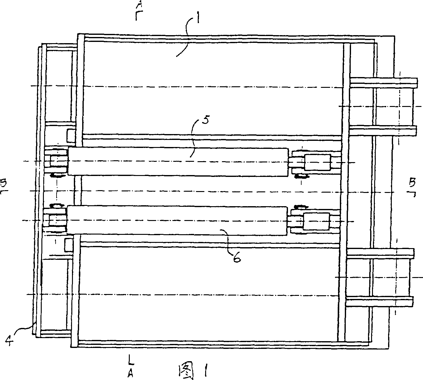
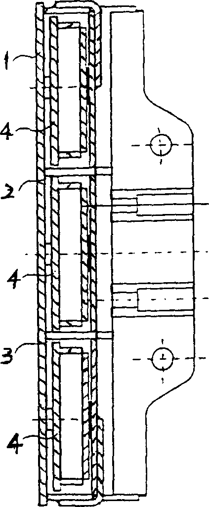
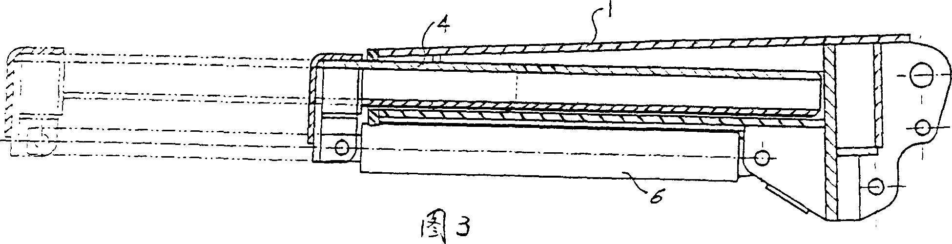
[0012] As shown in the figure, the design method of the telescopic beam assembly in the hydraulic support according to the present invention first sets the top beam 1 as a box-shaped body structure, and two guide partitions are arranged in the box cavity of the top beam 1 along its longitudinal direction. Plates 2 and 3 divide the box cavity into three chambers; a telescopic beam 4 of "E" shape is set in the box cavity of the top beam 1, and two jacks 5 and 6 that drive the expansion and contraction of the telescopic beam 4 are respectively It is arranged in the middle part of the outer surface of the bottom plate of the top beam 1 close to the two guide partitions 2 and 3; between the two sides of the beam plate of the telescopic beam 4 in the middle box cavity of the top beam 1 and the corresponding guide partitions 2 and 3 The fit gap between is less than the fit gap between the two sides of the telescopic beam 4 beam plate in the box cavity on both sides of the top beam 1 a...


PUM


Abstract

This invention discloses a method for designing extension bar assembly in the hydraulic support, which comprises the following steps: a) setting the top beam to box structure, setting two guide plates lengthwise in the box cavity and dividing the box cavity to three chambers; b) setting E shaped extension bar in the box cavity, setting two jacks used for driving the extension bar in the center of bottom surface of the top beam near the guide plates; the fit clearance between the extension bar bilateral in the middle box cavity and the corresponding guide plate is smaller than the fit clearance between the extension bar bilateral in the lateral box cavity and its corresponding guide plate.

Description

technical field [0001] The invention relates to an internal telescopic front beam in a hydraulic support, one of the supporting equipment of a fully mechanized coal mining face, in particular to a design method for an internal telescopic beam assembly in a hydraulic support. Background technique [0002] As a structural part of the hydraulic support, the inner telescopic beam is arranged at the front end of the hydraulic support. It is used in soft coal seams or coal seams where the top coal is easily broken to prevent the roof from falling off in the top coal goaf at the front end of the support, and it plays a timely support role on the hydraulic support. The inner telescopic beam is located inside the integral top beam or hinged front beam when it is not working, and extends to the coal wall under the action of the inner telescopic beam jack when in use. [0003] In the inner telescopic beam assembly, the inner telescopic beam and the hinged front beam or top beam all be...

Claims


Application Information

Patent Timeline
IPC IPC(8): E21D17/01
Inventor 焦承尧高有进史艳冰刘学丽杨惠敏穆燕英
Owner ZHENGZHOU COAL MINING MACHINERY GRP
Features
  • R&D
  • Intellectual Property
  • Life Sciences
  • Materials
  • Tech Scout
  • Unparalleled Data Quality
  • Higher Quality Content
  • 60% Fewer Hallucinations
Learn More