
Display device, color filter and electronic device

A technology of a display device and a color filter, which is applied to identification devices, lighting devices, static indicators, etc., can solve the problems of improving display quality and failing to obtain full resolution image quality.

Active Publication Date: 2005-11-23
INTELLECTUAL KEYSTONE TECH LLC
View PDF1 Cites 3 Cited by
  • Summary
  • Abstract
  • Description
  • Claims
  • Application Information

AI Technical Summary

Problems solved by technology

[0006] In the technology described in the above-mentioned patent documents, the inventors of the present invention found that although display colors in a wide wavelength region can be realized, sufficient resolution (resolution) and image quality cannot be obtained with this technology.
That is, although the expressiveness of colors is improved by using the above-mentioned technologies, the display quality may not necessarily be improved.

Method used


Image

  • Display device, color filter and electronic device
  • Display device, color filter and electronic device
  • Display device, color filter and electronic device

Examples


no. 1 Embodiment approach

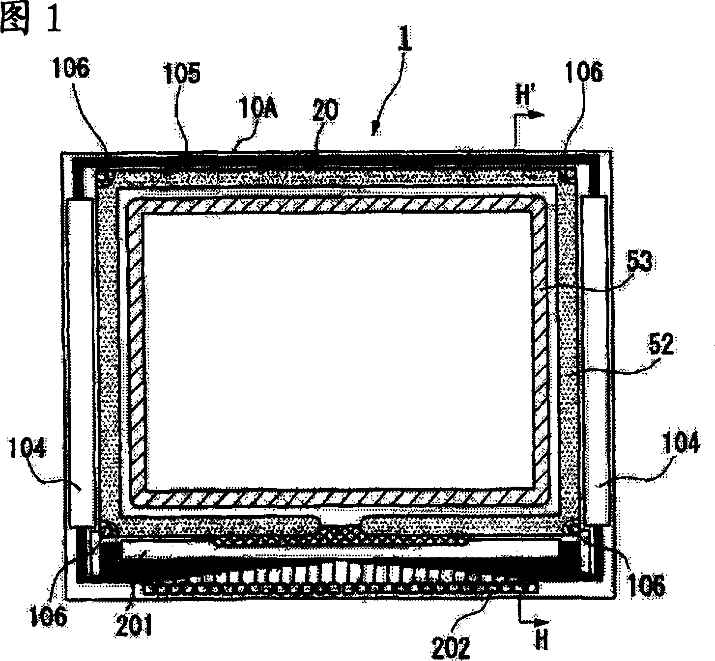
[0075] Below, refer to Figure 1- Figure 5 A first embodiment of the present invention will be described.

[0076] In this embodiment mode, an example of an active matrix transmission type liquid crystal display device using a thin film transistor (Thin Film Transistor, hereinafter referred to as TFT) as a switching element will be described.

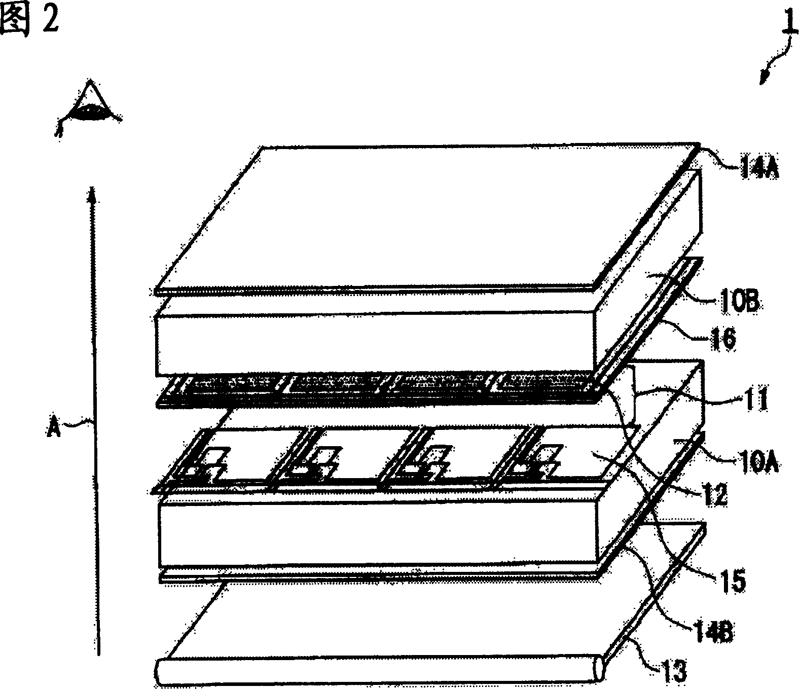
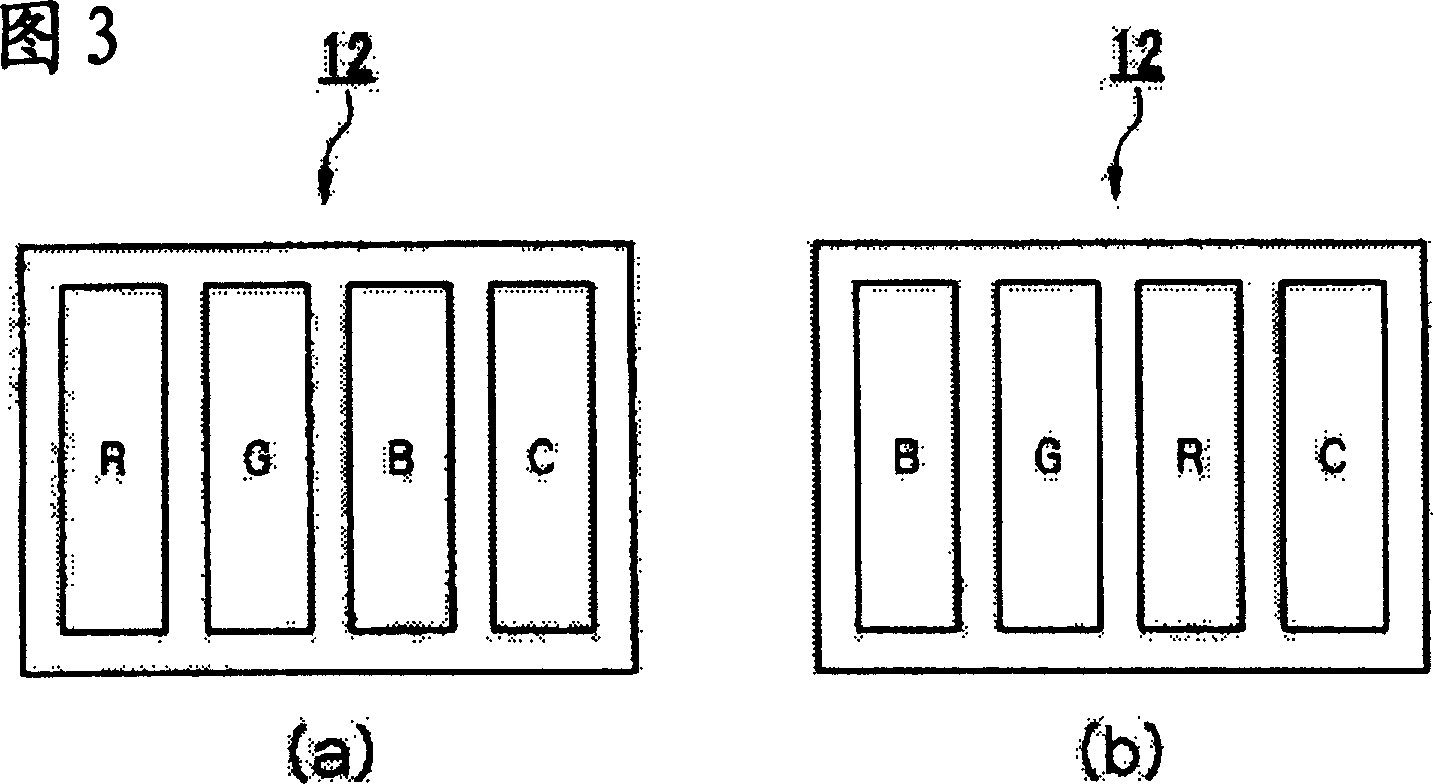
[0077] 1 is a plan view of each constituent element of the liquid crystal display device according to the present embodiment viewed from the counter substrate side, FIG. 2 is a perspective view for explaining the cross-sectional structure of the liquid crystal display device, and FIG. 3 is a color filter of the liquid crystal display device. device floor plan, Figure 4 is a graph showing the wavelength selection characteristics of the color filter, Figure 5 It is a figure for demonstrating the xy chromaticity characteristic of the color filter of a liquid crystal display device.

[0078]As shown in FIG. 1 , in the liquid crystal dis...

no. 2 Embodiment approach

[0128] Next, refer to Figure 6- Figure 10 A second embodiment of the present invention will be described.

[0129] In this embodiment, an example of an active matrix organic EL device using TFTs as switching elements will be described. In particular, it is a color organic EL display device having four kinds of polymer organic light-emitting layers of RGBC.

[0130] 6 is a diagram showing a planar structure of an organic EL device according to this embodiment, FIG. 7 is an enlarged cross-sectional view showing a pixel structure of an organic EL device, FIG. 8 is a planar configuration diagram of an organic EL layer of an organic EL device, and FIG. A graph showing the emission wavelength characteristics of an organic EL device, Figure 10 It is a graph for explaining the xy chromaticity characteristic of the light emitted by the organic EL device.

[0131] As shown in FIG. 6, the organic EL device (display device) 200 of this embodiment is configured to include an electrica...


PUM


Abstract

To provide a display device, a color filter, and an electronic apparatus, which can prevent the deterioration of resolution and display quality and can improve display characteristics. There is provided a display device comprising a plurality of dots in a unit pixel. The dots includes first to third dots having first to third peak wavelengths in the wavelength characteristics of emitted light, and a fourth dot having a fourth peak wavelength which is located between the first peak wavelength and the second peak wavelength, and has the fourth peak wavelength which is closer to the second peak wavelength than to the first peak wavelength, in the wavelength characteristics. The fourth dot is arranged not to be adjacent to the second dot, but is arranged to be adjacent to the first dot or the third dot.

Description

technical field [0001] The present invention relates to a display device, a color filter, and electronic equipment. Background technique [0002] Conventionally, various display forms have been proposed for display devices, for example, known CRT (cathode ray tube) displays, LCD (liquid crystal displays), organic electroluminescent devices (hereinafter referred to as organic EL devices), and plasma displays. . Such display devices all have the structure of three color points of R (red) / G (green) / B (blue) in the unit pixel, and various colors are realized by making the light intensity of the three color points different, and the Image display. [0003] However, in the natural world, there are wavelength regions of colors that cannot be displayed with only the three colors of R / G / B, and it is difficult to realize colors close to natural light. [0004] Therefore, in recent years, display devices capable of realizing colors closer to natural light have been proposed (for exa...

Claims


Application Information

Patent Timeline
IPC IPC(8): G02B5/20G02F1/1335G02F1/13357G09F9/30G09G3/20G09G3/32G09G3/36H01L51/50H05B33/12
CPCG09G2300/0452G09G3/3208G02F1/133514H01L27/3213G02F2201/52G09G3/3607G09G3/2003H10K59/351G02F1/1335
Inventor 前田强守屋英邦
Owner INTELLECTUAL KEYSTONE TECH LLC
Learn More