
Buttonhole sewing machine

A sewing machine and buttonhole technology, which is applied to sewing machine components, sewing equipment, textiles and papermaking, and can solve problems such as complex structures and inflexibility

Inactive Publication Date: 2005-11-02
DURKOPP ADLER AG
View PDF7 Cites 8 Cited by
  • Summary
  • Abstract
  • Description
  • Claims
  • Application Information

AI Technical Summary

Problems solved by technology

This structure is complex and not flexible enough

Method used


Image

  • Buttonhole sewing machine
  • Buttonhole sewing machine
  • Buttonhole sewing machine

Examples


Embodiment Construction

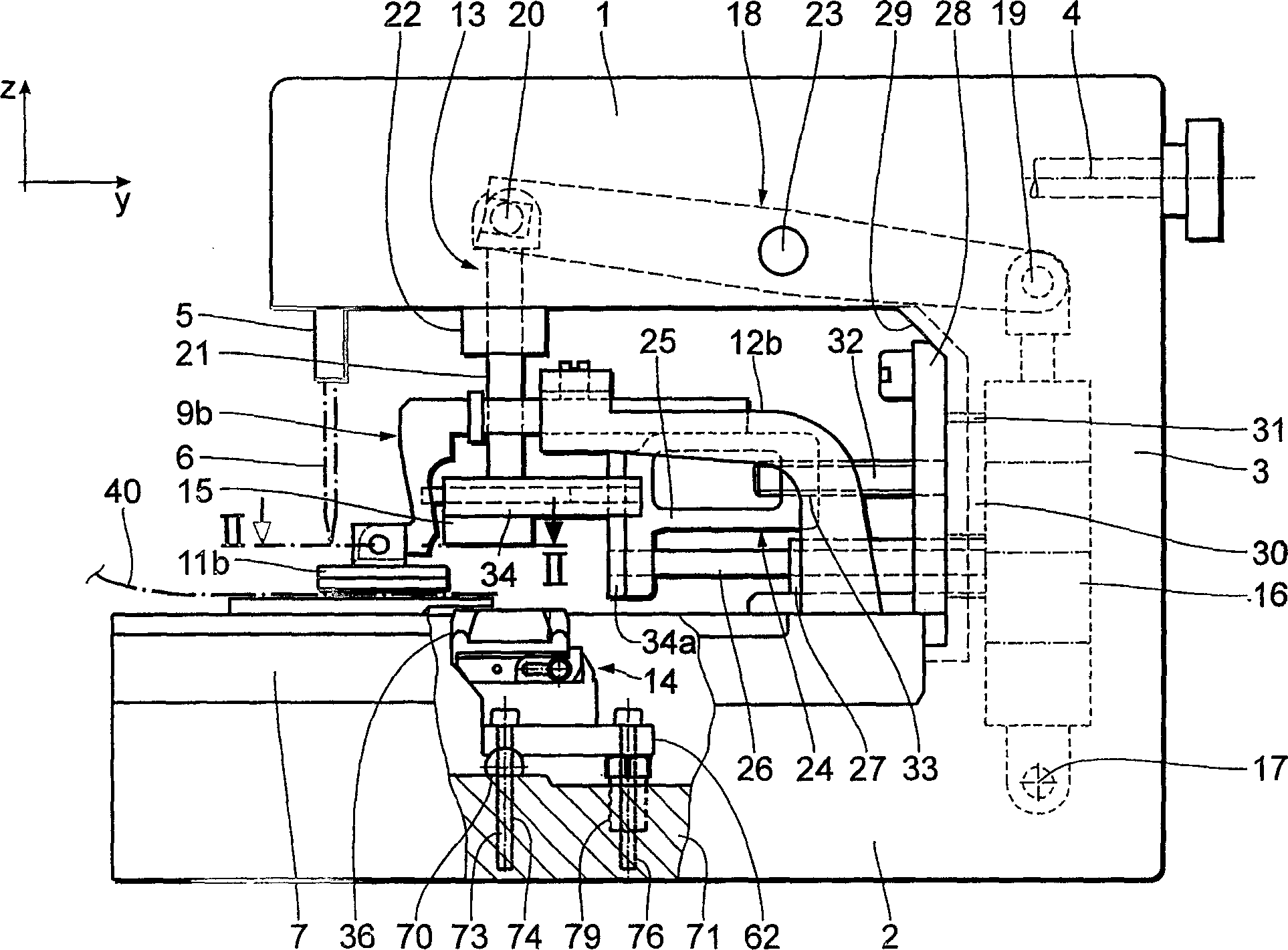
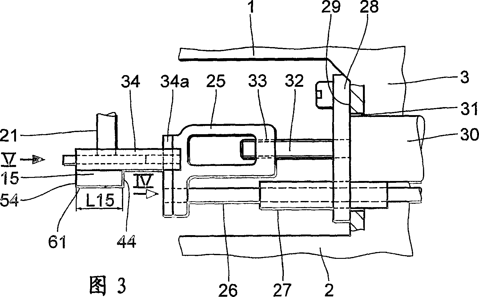
[0022] Depend on figure 1 It can be seen that the buttonhole sewing machine is C-shaped, ie it has an upper arm 1, a lower housing-shaped base plate 2 and a substantially vertical column 3 connecting the two. An arm shaft 4 is usually supported in the arm 1, which can be driven by a drive motor, not shown. The arrangement of such drive motors on such buttonhole sewing machines is known from DE10225511A and DE10225512A. The drive of a vertically displaceable needle bar 5 with needle 6 and a (reciprocating) pivoting drive for the needle generally derive from the arm shaft 4 .

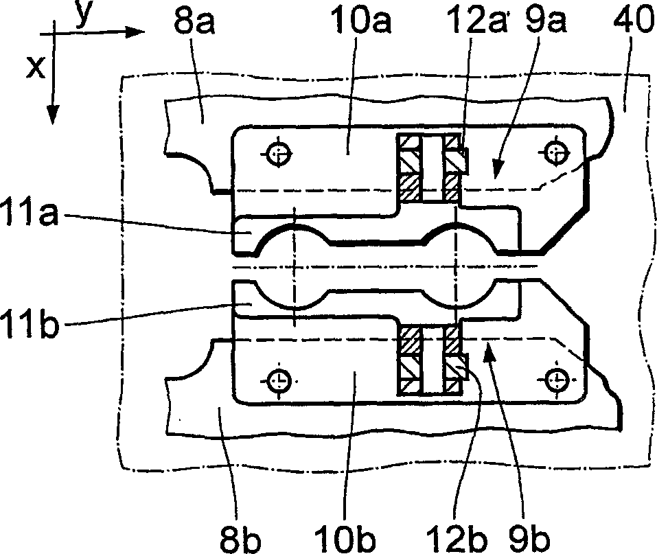
[0023] An x-y table 7 is provided on the base plate 2, here it is a cross slide movable in two horizontal coordinate directions, ie the x direction and the y direction. The x-y table 7 is generally made as known eg from DE19807771A1 (corresponding to US 6,095,066B). The drive of the x-y table 7 is carried out by means of drives not shown, i.e. the x-drive and the y-drive, wherein they are usually posit...


PUM


Abstract

A buttonhole sewing machine comprising an upper arm (1) with a needle (6), which can move up and down, and a base plate (2). A buttonhole cutting device (13), comprising a blade (36), which is arranged on the base plate (2) and consists of a cutting part (37) which extends in a straight line in direction y and an eye cutting part (38), is also provided. A cutting block (15) cooperates with the blade (36). The blade (36) and the cutting block (15) can be displaced by means of a motor in relation to each other in direction y.

Description

technical field [0001] The invention relates to a buttonhole sewing machine according to the preamble of claim 1 . Background technique [0002] A buttonhole sewing machine of this type is known from DE-PS291197 with a buttonhole cutting device having blades of different shapes and sizes arranged in the base plate. Depending on the desired shape of the buttonhole, a corresponding blade can be selected from a plurality of blades in a turret configuration. This device is very complicated. [0003] A device for producing buttonholes is known from US-PS2247305. One of the blades cooperates with a cutting block, wherein the engagement length, ie the overlapping portion of the blade and the cutting block, is adjustable so that buttonholes of variable length can be made. This structural form is more complicated and not flexible enough. [0004] Known from DE 10085290 T1 is a buttonhole sewing machine with a cutting device for cutting buttonholes with buttonholes. In this case,...

Claims


Application Information

Patent Timeline
Patent Type & Authority Applications(China)
IPC IPC(8): D05B3/06D05B3/08D05B37/02
CPCD05B3/06D05B3/08D05B37/02D05B37/04
Inventor J·菲舍尔T·诺尔特格
Owner DURKOPP ADLER AG
Learn More