Protection circuit of frequency converter

A technology for protecting circuits and frequency converters, applied in emergency protection circuit devices, circuit devices, battery circuit devices, etc., can solve problems such as large power loss of charging resistors, breakdown of charging resistors, etc.

Inactive Publication Date: 2005-11-02
DR JOHANNES HEIDENHAIN GMBH
View PDF0 Cites 0 Cited by
  • Summary
  • Abstract
  • Description
  • Claims
  • Application Information

AI Technical Summary

Problems solved by technology

[0009] If the intermediate circuit cannot be charged due to a short circuit in the intermediate circuit or a high discharge current, this means that the charging resistor has to cope with a significantly higher power loss, or the charging resistor breaks down

Method used


Image

  • Protection circuit of frequency converter

Examples


example

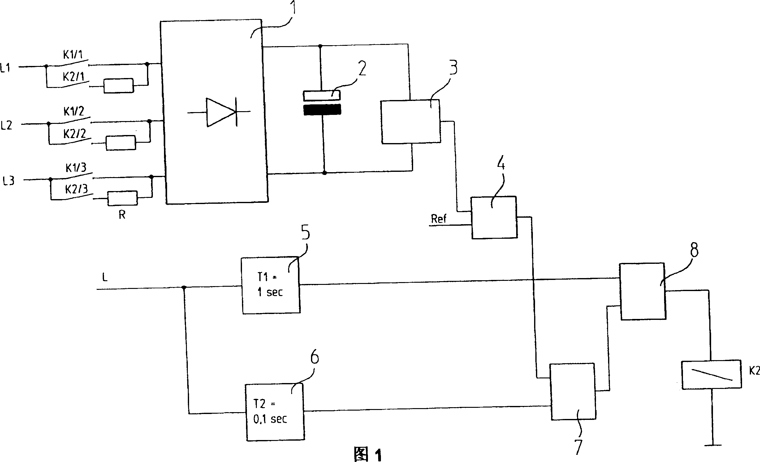
[0035] Calculation example: Grid voltage 3×400V~

[0036] Intermediate circuit voltage 565V =

[0037] Intermediate circuit capacitance 2mF

[0038] Charging resistor 3×10 ohms

[0039] Dissipated energy in the resistor 1 / 2CU 2 = 319Ws (during trouble-free charging of the intermediate circuit)

[0040] In the case of a short circuit in the intermediate circuit, in the case of the longest charging time of 1 second, the loss energy is 3×((230V) 2 / 10 ohms) = 15870Ws.

[0041] In the application of the present invention, under the situation that charging is interrupted after 0.1 second, generation loss energy is

[0042] 15870×0.1=1587Ws.


PUM


Abstract

The voltage of the intermediate circuit of a frequency converter is monitored, while the intermediate circuit is charged via charging resistors. When the voltage has not reached at least a reference voltage during a specific time constant, the charging process is interrupted prematurely. The reference voltage is selected to be considerably lower than the operating voltage of the intermediate circuit. The reference voltage may be less than half of the operating voltage of the intermediate circuit.

Description

technical field [0001] The invention relates to a protection circuit of a frequency converter. Background technique [0002] Frequency converters are used to convert fixed-frequency alternating current, eg from the grid, into variable-frequency alternating current for operating electric motors. [0003] The frequency converter has a rectifier circuit, a downstream intermediate circuit with intermediate circuit capacitors, and a downstream inverter. [0004] When switching on the inverter, the intermediate circuit capacitors must first be charged. At this point, very high currents can occur if suitable measures for limiting the current are not taken. This means that the intermediate circuit capacitor behaves like a short circuit in the uncharged state. [0005] Therefore, a charging resistor that limits the charging current is used. These charging resistors may not be connected across until the intermediate circuit capacitor is at least largely fully charged. [0006] If...

Claims


Application Information

Patent Timeline
IPC IPC(8): H02M5/27
Inventor N·胡伯S·格拉夫
Owner DR JOHANNES HEIDENHAIN GMBH
Why Eureka
Try Eureka