Taumelscheiben-verstellkompressor
A technology of volumetric compressors and wobble plates, applied in the fields of wobble plate compressors and wobble plate variable volume compressors, which can solve difficult production and assembly, difficult assembly of constant speed universal joints, and complex rotation stop mechanism Taper and other problems to achieve the effect of ensuring rigidity and small vibration
- Summary
- Abstract
- Description
- Claims
- Application Information
AI Technical Summary
Problems solved by technology
Method used
Image
Examples
no. 1 example
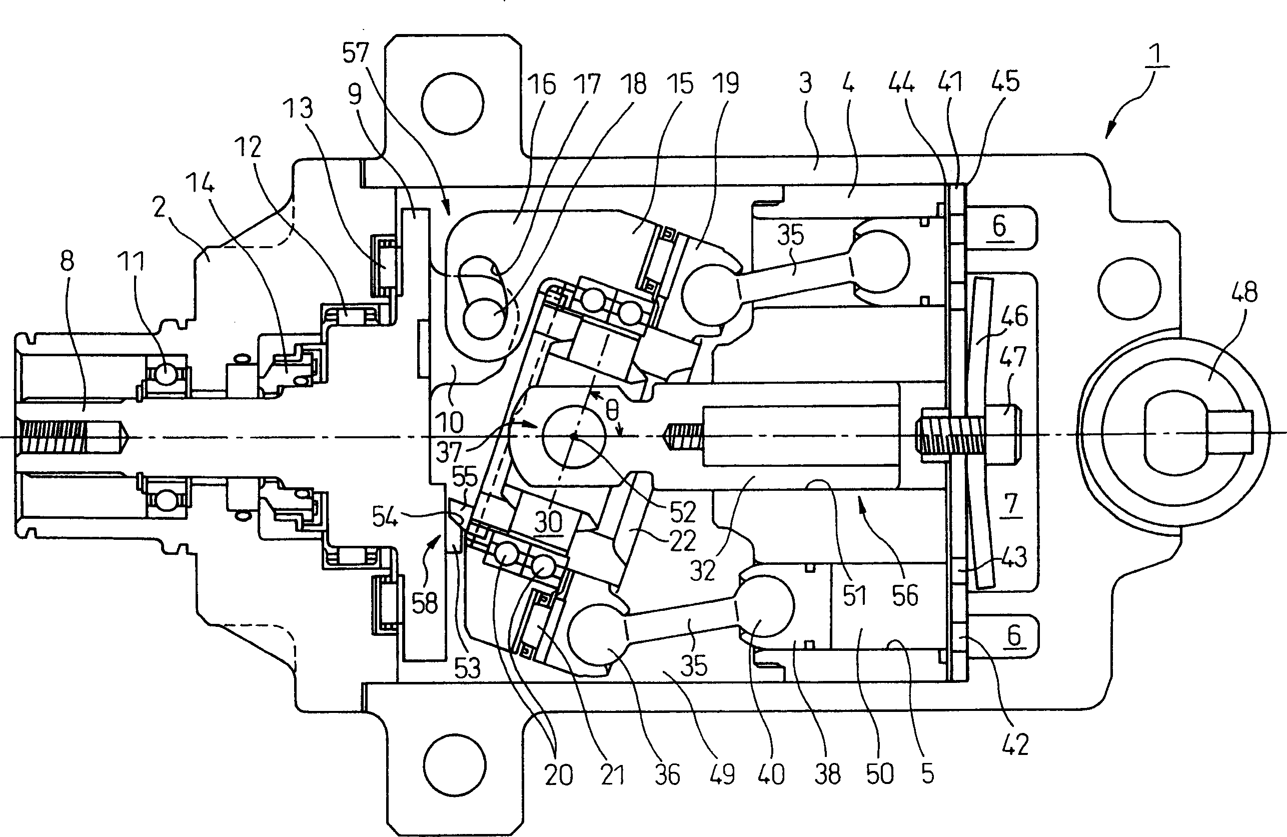
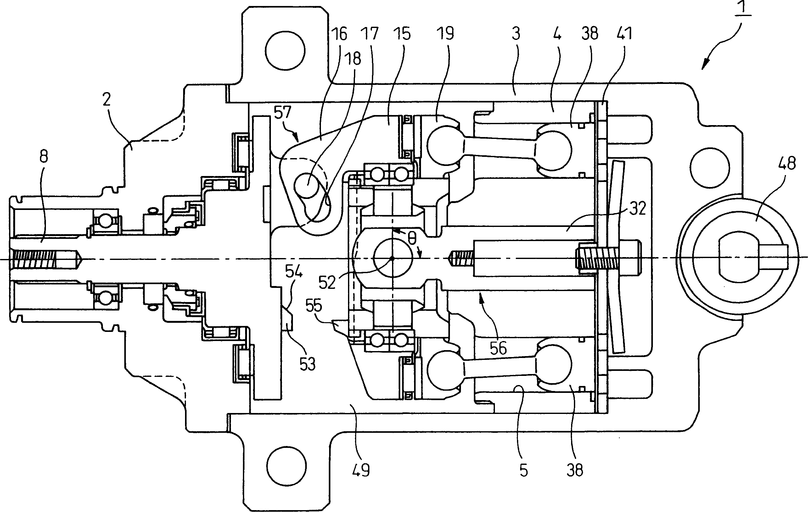
[0038] Figure 1 to 3 The configuration and operating conditions of the wobble plate type variable displacement compressor according to the first embodiment of the present invention are shown. figure 1 The overall configuration of the compressor 1 under the operating conditions that provide the maximum displacement (100%) is shown. figure 2 Shown in enlarged detail figure 1 The main part. image 3 The operating conditions that provide the minimum displacement (0%) are shown. In these figures, reference numeral 2 denotes a front end cover which is a part of the casing of the compressor 1. Reference numeral 3 denotes a housing integrated with the front end cover 2 by a fastening device not shown in the figure, such as a bolt. The cylinder 4 is fixed in the housing, and a plurality of (for example, five) cylinder bores 5 are figure 1 In the horizontal direction (in the axial direction of the drive shaft appearing later), they are arranged approximately equidistantly around the ce...
no. 2 example
[0066] The load supporting portion 8 in the first embodiment engages and effectively operates when the radial load reaches the maximum 100% capacity or near 100% capacity. Figure 6 The second embodiment shown in is characterized in that the specific load supporting portion 62 is effective not only in 100% capacity but also in a wide high-displacement operation range up to about 70% capacity. In the load supporting portion 62 in the second example, an inclined surface 64 composed of a curved surface is formed on the protrusion 63 provided on the disk portion 9 of the drive shaft 8, and the protrusion on the side of the drive plate 15 that is in contact with the inclined surface 64 The shape of the distal end of the protrusion 65 is a curved surface with a small diameter such as an arc.
[0067] Therefore, under the operating conditions of the compressor 66 of the second example, the radial load acting on the unit blocks of the drive plate 15 and the wobble plate 19 is transmitted ...
no. 3 example
[0072] Figure 8 Is a longitudinal cross-sectional view showing the overall configuration of the wobble plate type variable displacement compressor according to the third embodiment under the operating condition that provides the maximum displacement (100% capacity), Figure 8 Showing offer Figure 7 The minimum displacement (0% capacity) of the compressor in the operating conditions.
[0073] The third embodiment uses a cage-type constant-speed universal joint 68 that is essentially known as a rotation stop mechanism for prohibiting the rotation of the outer ring 22 and the wobble plate 19. Since the configuration of the rotation stop mechanism and its peripheral portion constitutes a feature of the third embodiment, it will be described in detail. Since the basic structure is the same as that of the related art, the description of those parts that have already been explained will be omitted.
[0074]Next, the structure of the rotation stop mechanism and its peripheral portion, ...
PUM
 Abstract
Description
Claims
Application Information
 - R&D
- Intellectual Property
- Life Sciences
- Materials
- Tech Scout
- Unparalleled Data Quality
- Higher Quality Content
- 60% Fewer Hallucinations
Browse by: Latest US Patents, China's latest patents, Technical Efficacy Thesaurus, Application Domain, Technology Topic, Popular Technical Reports.
© 2025 PatSnap. All rights reserved.Legal|Privacy policy|Modern Slavery Act Transparency Statement|Sitemap|About US| Contact US: help@patsnap.com


