
Adjustable casting mold

A mold and cold casting technology used in the field of molds for direct cold casting of metal ingots

Inactive Publication Date: 2005-10-12
HATCH LTD
View PDF0 Cites 7 Cited by
  • Summary
  • Abstract
  • Description
  • Claims
  • Application Information

AI Technical Summary

Problems solved by technology

[0006] Although various types of adjustable molds for direct chill casting have been developed in the past, there is still a need for effective and simple and reliable mold systems for direct chill casting

Method used


Image

  • Adjustable casting mold
  • Adjustable casting mold
  • Adjustable casting mold

Examples


Embodiment Construction

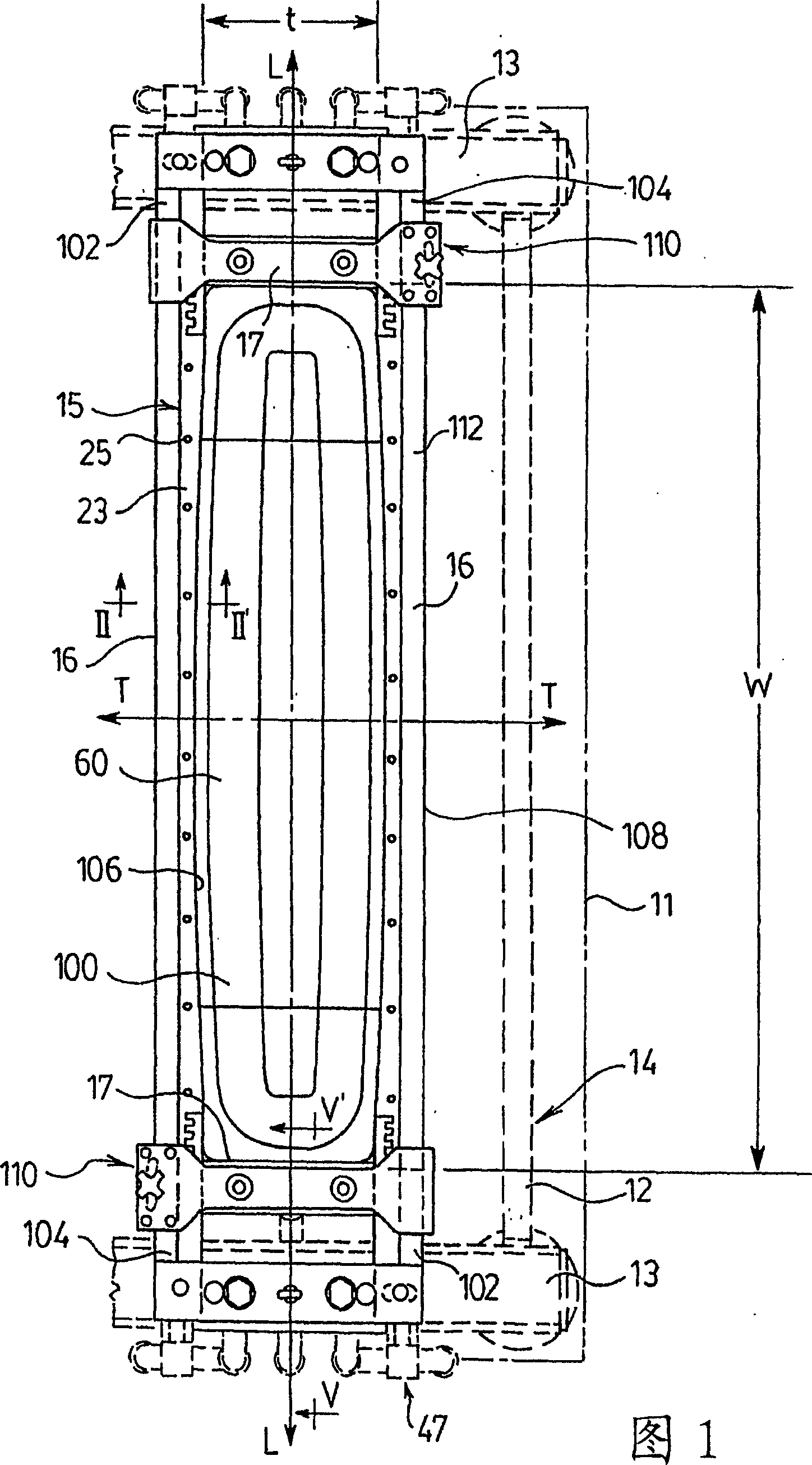
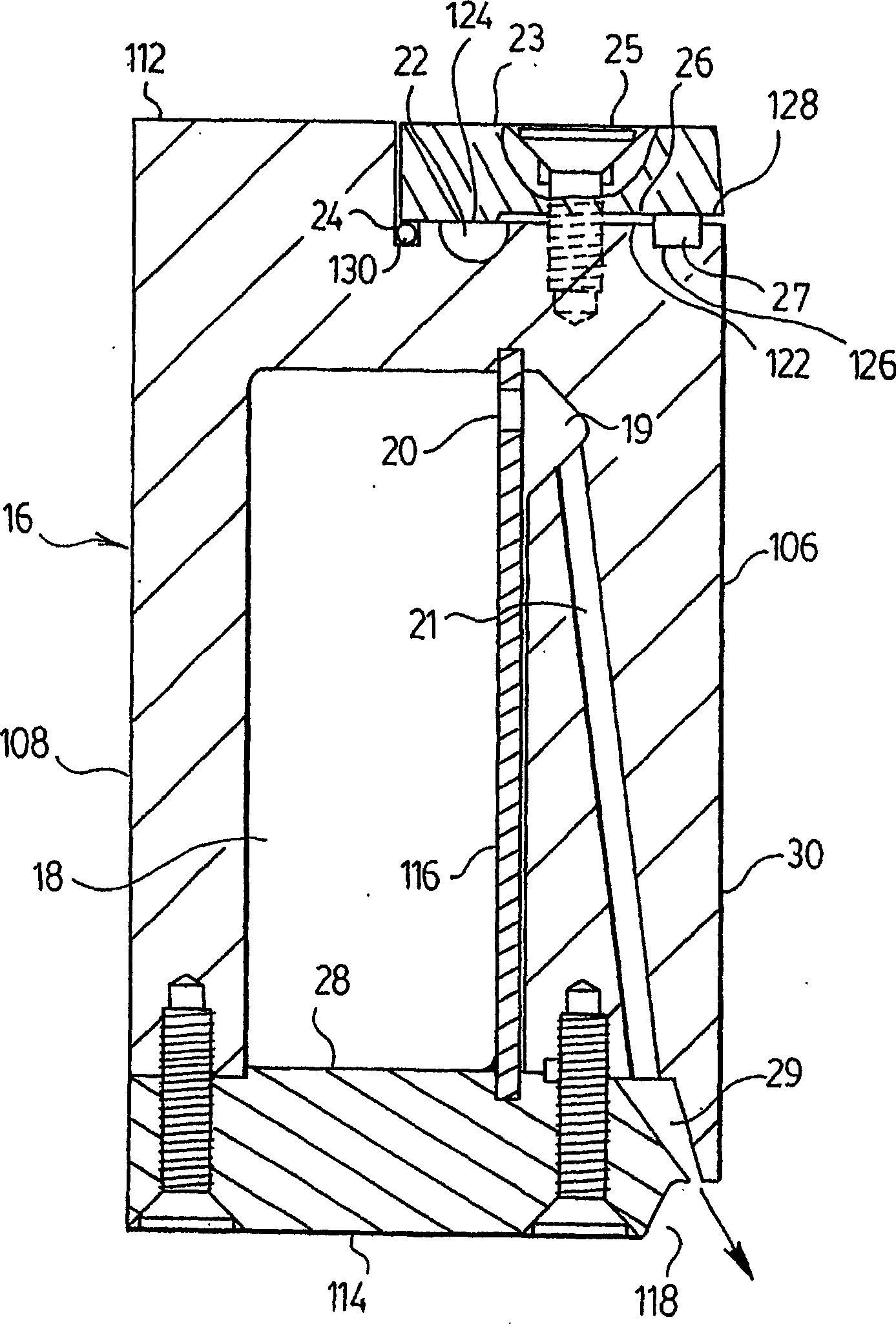
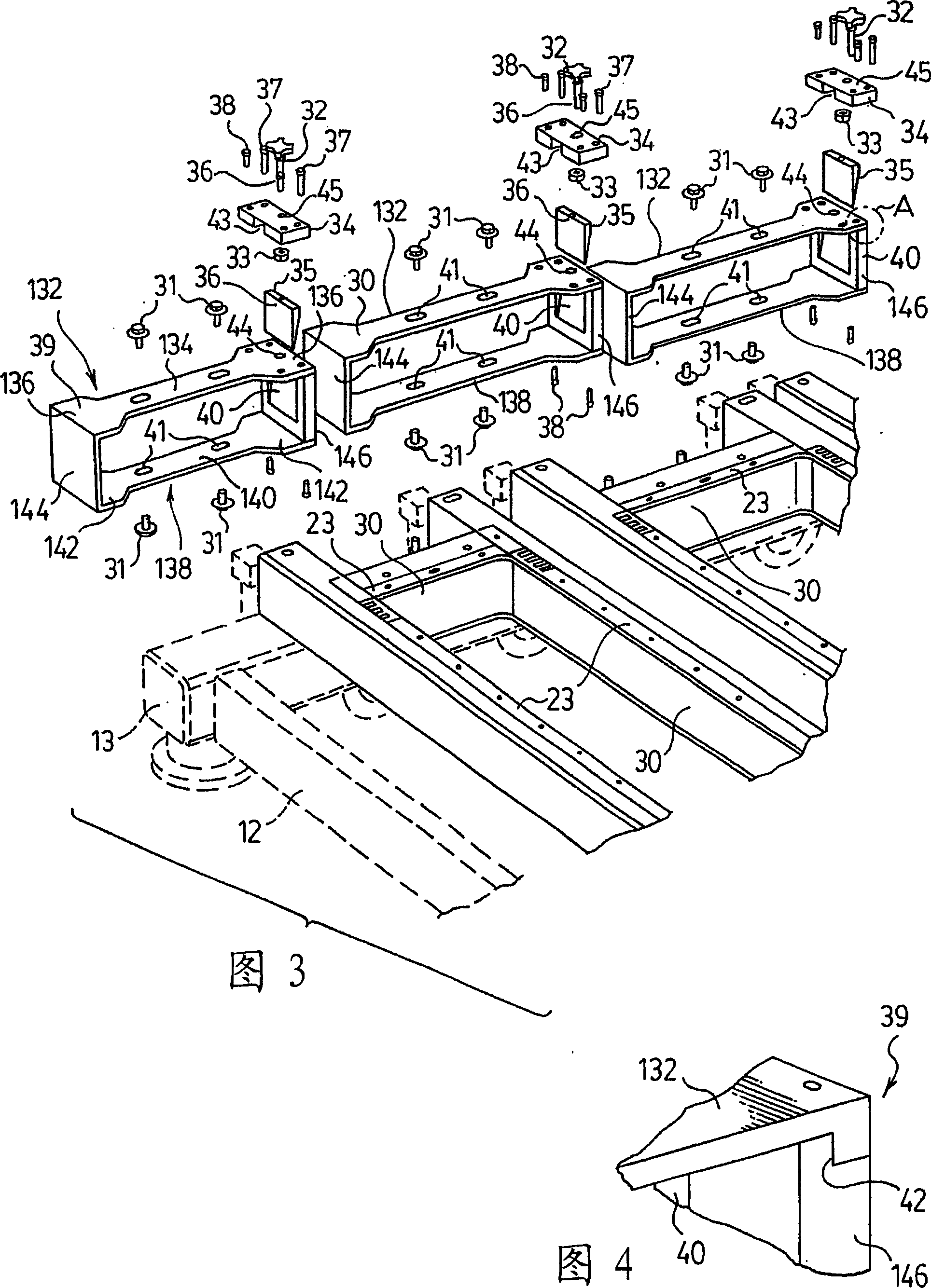
[0038] Figure 1 shows the main components of a preferred adjustable mold assembly 15 of the present invention. The die assembly 15 includes a pair of opposing side walls 16 and a pair of opposing end walls 17 that together define a generally rectangular die space 100 having an open top through which molten metal enters the die 15 . The relatively longer side walls 16 are substantially parallel to each other and to the longitudinal axis L. As shown in FIG. The relatively short end walls 17 are parallel to each other and to the transverse axis T. As shown in FIG. The broad faces and short edges of the ingot (not shown) are formed along the side walls 16 and along the end walls 17 . The nominal width w of the ingot is defined by the longitudinal distance between the end walls 17 , while the nominal thickness t of the ingot is defined by the length of the end walls 17 (measured parallel to the transverse axis T).

[0039] Each side wall 16 has a first end 102, a second end 104, ...


PUM


Abstract

An adjustable mold for direct chill casting of metals has longitudinally movable end walls which are clamped between the mold side walls during casting. Each end wall is secured to a sliding carriage which supports the end wall and allows it to be moved along the end portions of the side walls. The sliding suspender has a clamping mechanism which applies a clamping force to one or both of the side walls, the force being transversely directed through a center of the end wall. The side walls are pivotable relative to one another to allow clamping and unclamping of the end walls. Preferably, one end of each side wall is pivotable so as to transversely displace the opposite end of the side wall, with the pivoting ends of the respective side walls preferably being opposite one another across the mold.

Description

technical field [0001] The present invention relates to molds for direct chill casting of metal ingots, and more particularly to such molds having at least one adjustable mold wall. Background technique [0002] Sheet metal ingots of rectangular cross-section are used in a variety of industries. The ingot is usually cast by a method called "direct chill cast". The method employs an open-top mold with four fluid-cooled walls, two relatively long side walls and two relatively short end walls. The broad faces of the ingot are formed along the side walls, while the short edges of the ingot are formed along the end walls. [0003] Direct chill casting molds have a bottom block that moves downward during the casting operation. The molten metal to be cast is poured into the open top of the mold and the bottom block moves downwards away from the mold as casting takes place. [0004] The molten metal is first cooled by contact with the fluid-cooled mold walls, forming a solidifie...

Claims


Application Information

Patent Timeline
Patent Type & Authority Applications(China)
IPC IPC(8): B22D11/04B22D11/049B22D11/05B22D11/07B22D11/08
CPCB22D11/0403B22D11/08B22D11/07B22D11/049B22D11/05
Inventor 盖伊·勒布朗朱利安·勒米厄詹姆斯·P·安森唐纳德·A·威尔逊
Owner HATCH LTD
Learn More