
Pivot rotating mechanism of displaying device

A pivoting mechanism and display technology, applied in the field of pivoting mechanisms, can solve the problems of high failure rate, complex structure and high technical requirements

Inactive Publication Date: 2005-10-12
JIIN MING IND
View PDF0 Cites 6 Cited by
  • Summary
  • Abstract
  • Description
  • Claims
  • Application Information

AI Technical Summary

Problems solved by technology

[0005] The technical problem to be solved by the present invention is to provide a pivoting mechanism for a display, which solves the problems of complex structure, high technical requirements and high failure rate in the prior art

Method used


Image

  • Pivot rotating mechanism of displaying device
  • Pivot rotating mechanism of displaying device
  • Pivot rotating mechanism of displaying device

Examples


Embodiment Construction

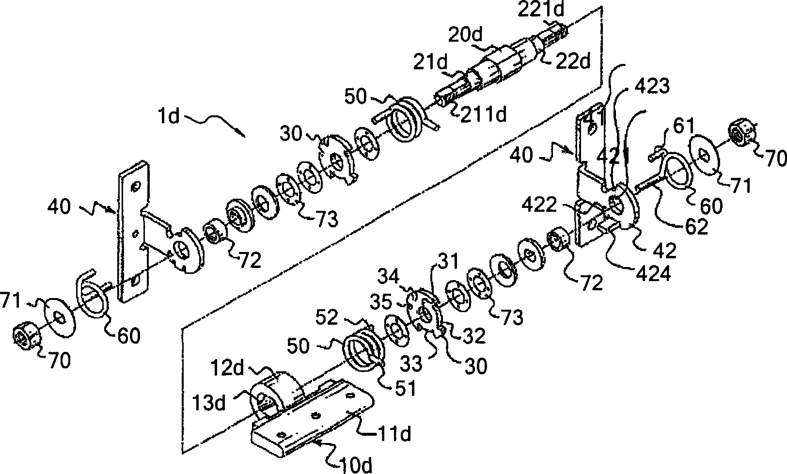
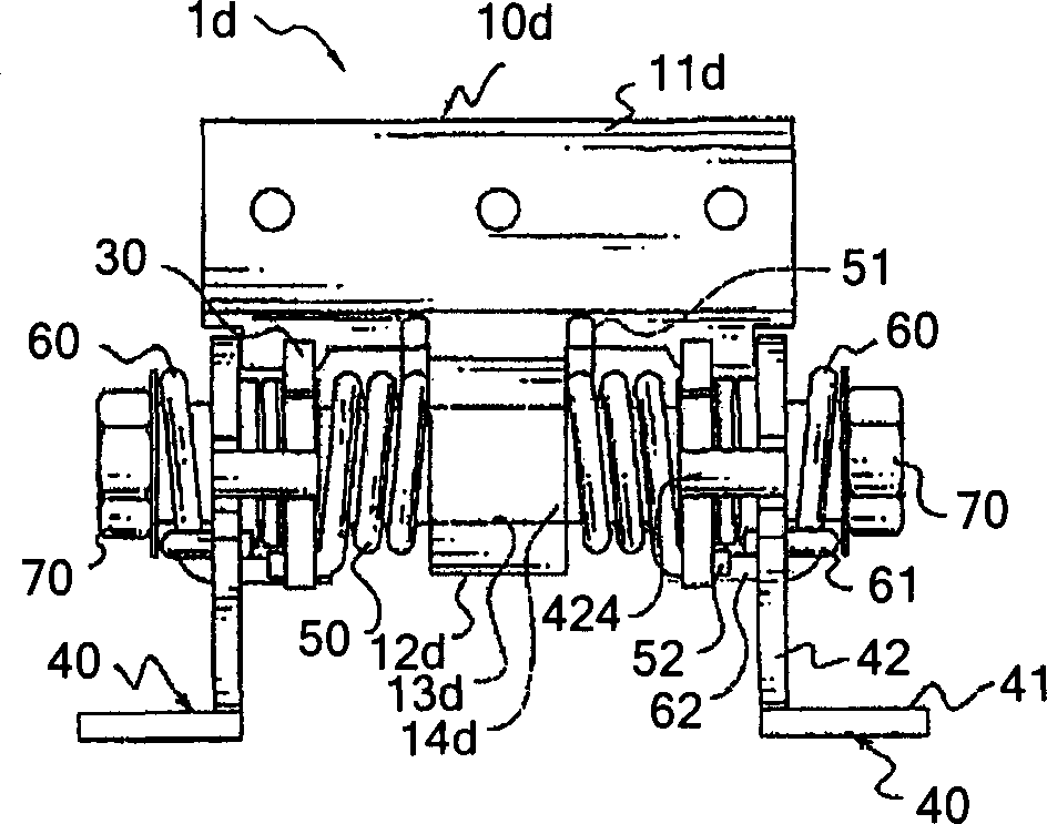
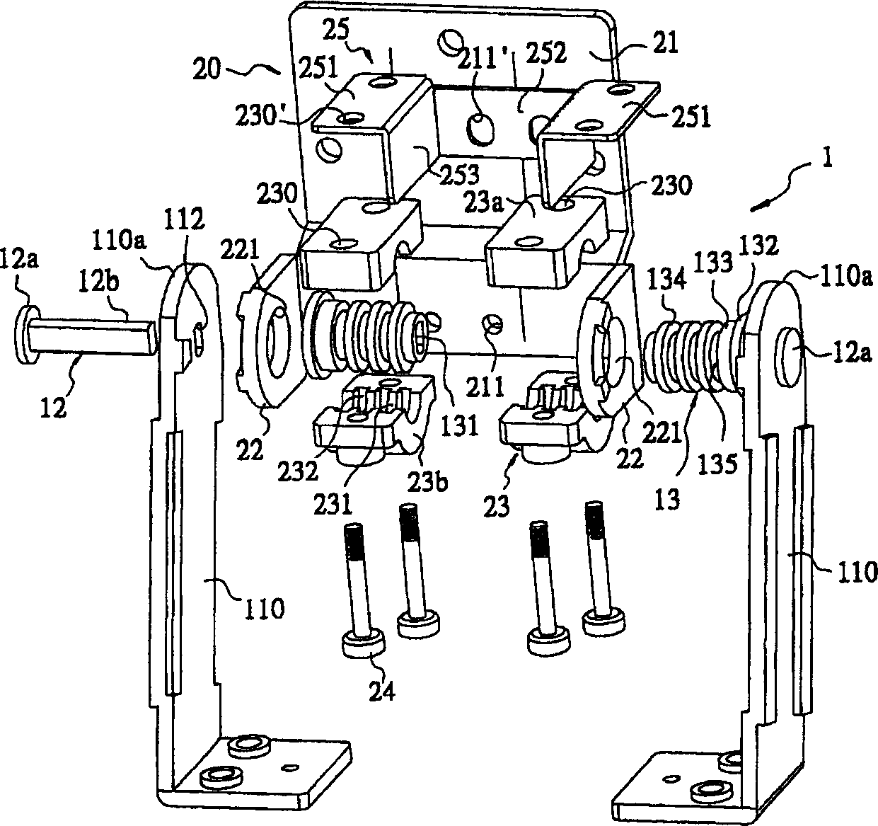
[0068] First, please refer to figure 2 and compare image 3 and Figure 4 , the display pivoting mechanism 1 of the present invention, especially the pivoting mechanism used between the screen and the seat such as liquid crystal display monitor (LCD Monitor), liquid crystal display TV (LCD TV), etc., can be balanced at any angle; It mainly includes: a fixing assembly 10, equipped with a seat 11 for balancing; a pair of brackets 110, one end of which is fixed on the surface of the seat 11 via a plurality of screws 111, and the other end is a free end 110a extending vertically with a suitable A bolt hole 112 is formed at the center of the free end 110a of the bracket 110, and the bolt hole 112 is non-uniformly circular and flat. A pair of metal bolting pins 12, the first end 12a has a cap, the second end 12b is a non-symmetrical circular flat shape corresponding to the bolt hole 112, and passes through the free end of the bracket 110 from the outside to the inside. The bolt ...


PUM


Abstract

A pivot mechanism for turning over display screen consists of a fixing component; base; a pair of support frames with bolt-pin; a pair of bushes; being set on bolt - pin; multiple radial ring rib rounding external surface of bush; a movable component including erection part for holding display screen, integrated shaft station having shaft hole formed with multiple slots on surface. The mechanism is prepared with heavy friction force so it can have display screen balanced at any angle.

Description

technical field [0001] The invention relates to a pivoting mechanism, in particular to a pivoting mechanism for a display which can balance the display screen at any angle. Background technique [0002] General displays such as liquid crystal display (LCD), thin film transistor (TFT) liquid crystal display, etc., have been widely used in PC personal computers or NB notebook computers, etc. due to the characteristics of lightness, thinness and miniaturization. The pivoting mechanism between the two is commonly used to pass a mandrel through the connecting member between the two, put on the disc-shaped washer and then tighten it with a nut, so that a friction force is generated when the two rotate; or , such as the rotating shaft commonly used in NB notebook computers, there is a frictional force between the tightly fitted sleeve and the mandrel, so that the display screen can be balanced at any angle. However, ordinary people can understand or have this experience that after...

Claims


Application Information

Patent Timeline
IPC IPC(8): G02F1/1333
Inventor 林宽礼
Owner JIIN MING IND
Learn More