
Automatic welding machine for annular seam in specially shaped tank

An automatic welding machine and tank body technology, applied in welding equipment, welding equipment, arc welding equipment, etc., can solve the problems of low production efficiency, large differences, and large differences in the appearance of welds, and achieve automatic and efficient welding. effect, quality assurance

Inactive Publication Date: 2005-09-28
刘宪福
View PDF0 Cites 31 Cited by
  • Summary
  • Abstract
  • Description
  • Claims
  • Application Information

AI Technical Summary

Problems solved by technology

At present, manual welding is generally used in China. The welding quality varies greatly due to the technical quality of the workers, and the appearance of the welds varies greatly. The welding quality cannot be guaranteed and the production efficiency is low.

Method used


Image

  • Automatic welding machine for annular seam in specially shaped tank
  • Automatic welding machine for annular seam in specially shaped tank
  • Automatic welding machine for annular seam in specially shaped tank

Examples


Embodiment 1

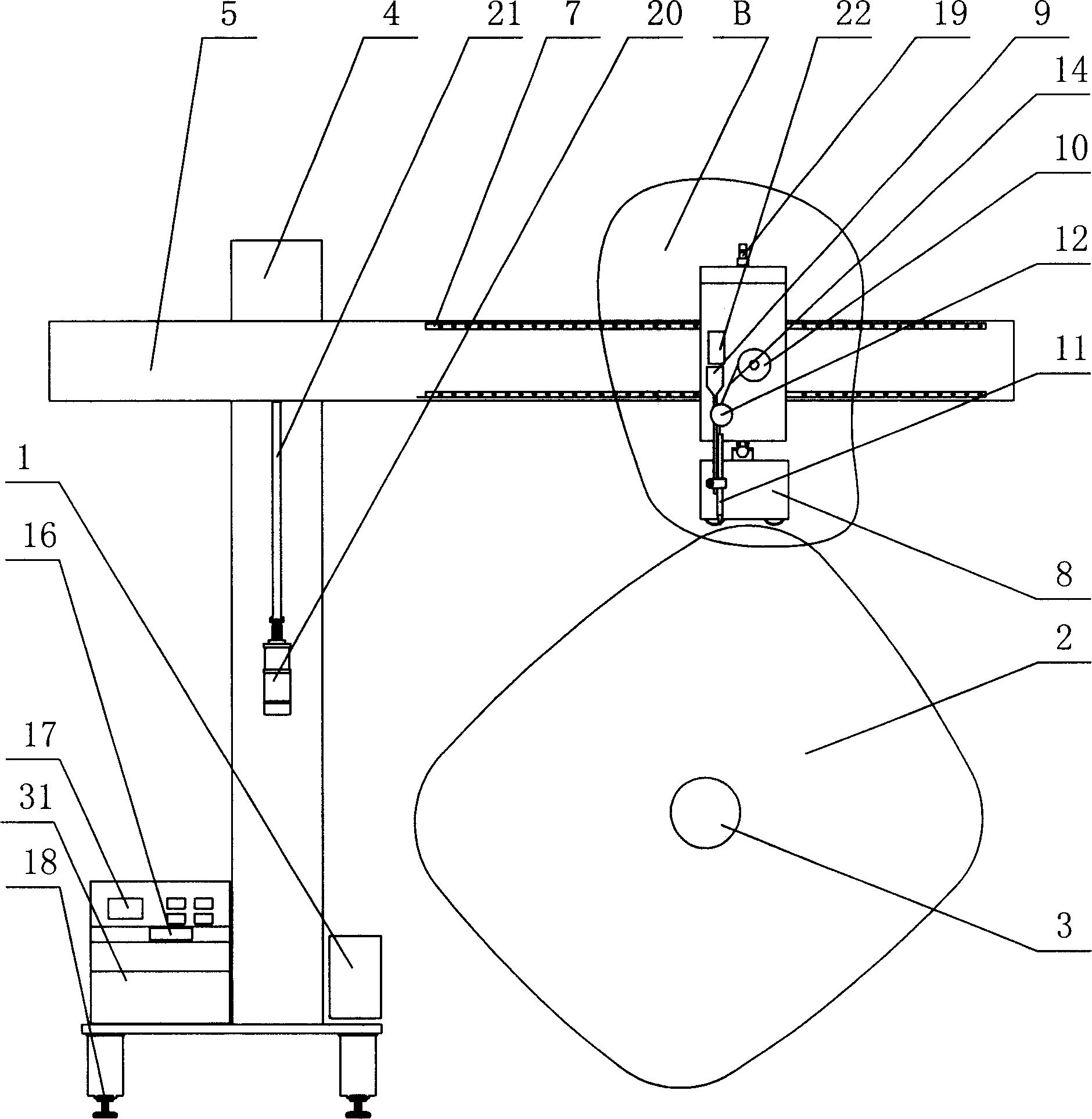
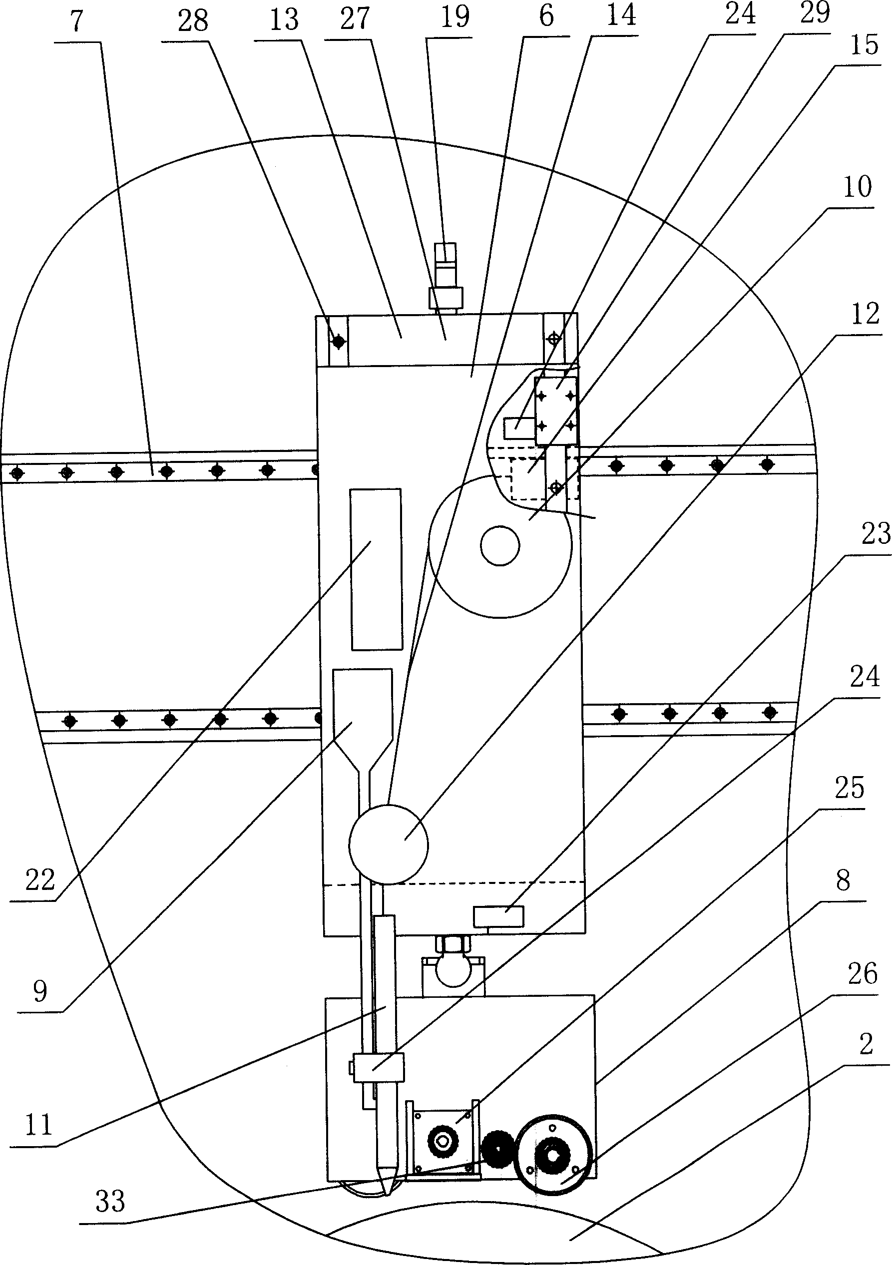
[0013] Embodiment one: the present invention comprises welding machine 1, special-shaped tank body 2, and rotating device 3 is installed on tank body 2, and a driving track 18 is arranged on one side of tank body 2, and support 4 is arranged on driving track 18, A crossbeam 5 is installed on the support 4, and it is characterized in that: a transverse guide rail 7 is fixedly installed on the crossbeam 5, and a transverse slide plate 13 is installed on the guide rail 7, and a slide block 15 is installed on one side of the slide plate 13, the slide plate 13 On the other side, a longitudinal guide rail 28 is fixedly installed, and a longitudinal slide plate 6 with a longitudinal slide block 29 is installed on the longitudinal guide rail 28. On the longitudinal slide plate 6, a welding wire reel 10, a welding wire conveying device 12 and a welding wire conveying device 12 for winding welding wire 14 are fixedly connected. The bucket 9 is fixedly connected with a trolley 8 at the bo...

Embodiment 2

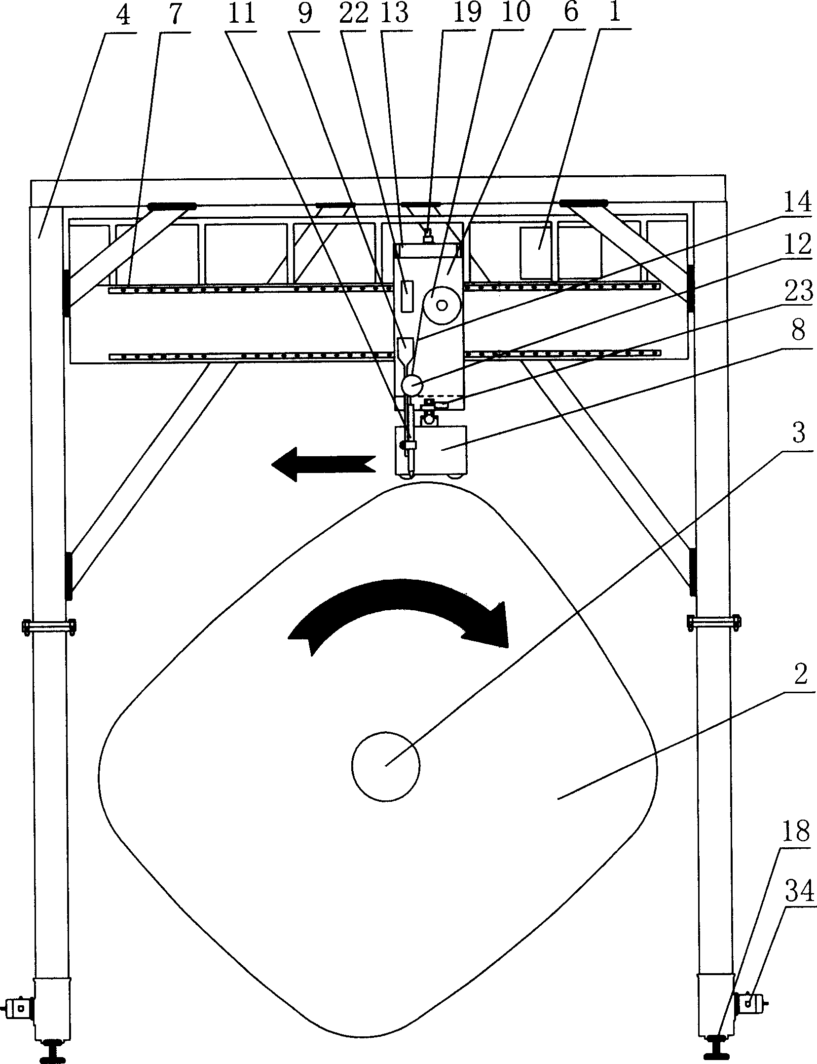
[0015] Embodiment two: if image 3 , Figure 4 As shown, the difference from Embodiment 1 mainly includes the following points: the form of the support 4 is changed from a single operation frame type on one side of the tank body 2 to a gantry type across both sides of the tank body 2, and on the brackets 4 on both sides, respectively A driving motor 34 is provided to realize that the support 4 automatically walks along the track 18 . The single beam 5 in the first embodiment is changed to a welding platform 30, and the welding machine 1 is installed on the welding platform 30; the platform lifting motor 20 is changed from one to two on both sides. Other structures are the same as in Embodiment 1.

[0016] Compared with Embodiment 1, although the cost of this method is higher, it can greatly increase the stability and automaticity of the whole system, further ensuring the efficiency and quality of welding.

[0017] The welding form can adopt submerged arc welding or MIG / MAG ...


PUM


Abstract

The automatic welding machine for annular seam in specially shaped tank includes welding machine, specially shaped tank, rotating device installed on the tank, overhead crane track on the side of the tank, support on the overhead crane track, and welding platform on the support. The present invention features the horizontal track fixed on the welding platform with installed horizontal sliding plate, the longitudinal track installed on the other side of the sliding plate with installed longitudinal sliding plate, welding wire disc with wound welding wire and welding wire transmission unit on the longitudinal sliding plate, bogie with welding gun, driving motor and distance sensor connected to control via cable and fixed to the lower part of the longitudinal sliding plate, and the controller connected also to the driving motor in the bogie and the rotating device on the tank. The present invention has the features of automatic welding, high efficiency and good welding effect.

Description

technical field [0001] The invention relates to a welding auxiliary device, in particular to a device for circular seam welding of special-shaped tank bodies. Background technique [0002] my country's welding auxiliary equipment and appliance manufacturing industry has developed rapidly on the original basis. There are three major types of welding auxiliary equipment—welding manipulators, positioners, and roller frames, which have been expanded to various welding special complete sets of equipment. Solved the automatic welding technology of spherical tanks and the girth welding technology of cylindrical storage tanks, but none of them could solve the problem of girth welding of special-shaped tanks, such as oval and square oval tanks. At present, manual welding is generally used in China. The welding quality varies greatly due to the technical quality of workers, and the appearance of weld seams varies greatly. The welding quality cannot be guaranteed and the production effi...

Claims


Application Information

Patent Timeline
IPC IPC(8): B23K9/032B23K9/095B23K9/12B23K37/047
Inventor 刘宪福王洪军申伟
Owner 刘宪福
Learn More