
Matrix form push installing method for large span deep space steel structure

A steel structure, large-span technology, applied in building structure, construction, etc., can solve problems such as inability to install tire frames and cranes, low rigidity, etc.

Inactive Publication Date: 2005-09-21
SHANGHAI MECHANIZED CONSTR GRP
View PDF0 Cites 7 Cited by
  • Summary
  • Abstract
  • Description
  • Claims
  • Application Information

AI Technical Summary

Problems solved by technology

[0002] At present, super-large overall steel structure buildings are widely used. Some existing steel structures with large spaces are generally lifted on site, installed at high altitude, and gradually complete the overall structure installation. However, when encountering various conditions on the construction site Due to the limitation, it is impossible to install the tire frame and the layout of the crane as required on the construction site, especially the limitation of the maximum lifting capacity and lifting moment of the crane. There are some difficult problems in the installation of large-scale space steel structures with large spans. If the installation is located at a high altitude, the structure itself has low stiffness, and the structure has multiple degrees of freedom and structural stability during installation

Method used


Image

  • Matrix form push installing method for large span deep space steel structure
  • Matrix form push installing method for large span deep space steel structure
  • Matrix form push installing method for large span deep space steel structure

Examples


Embodiment Construction

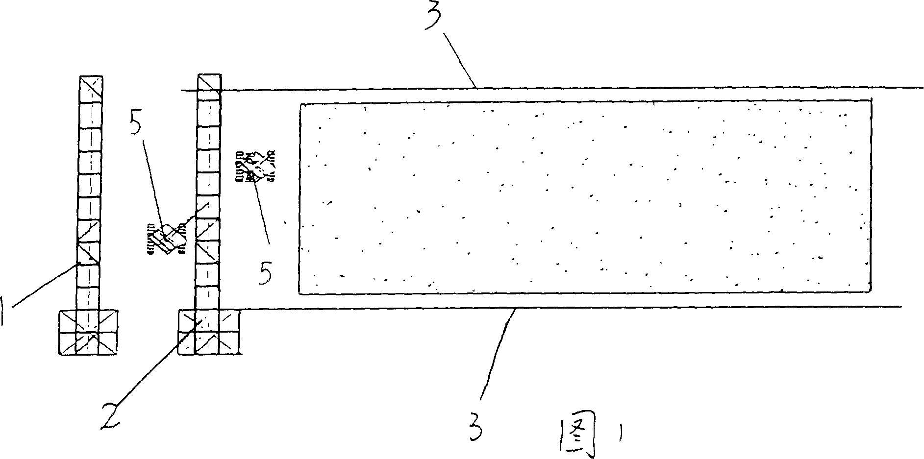
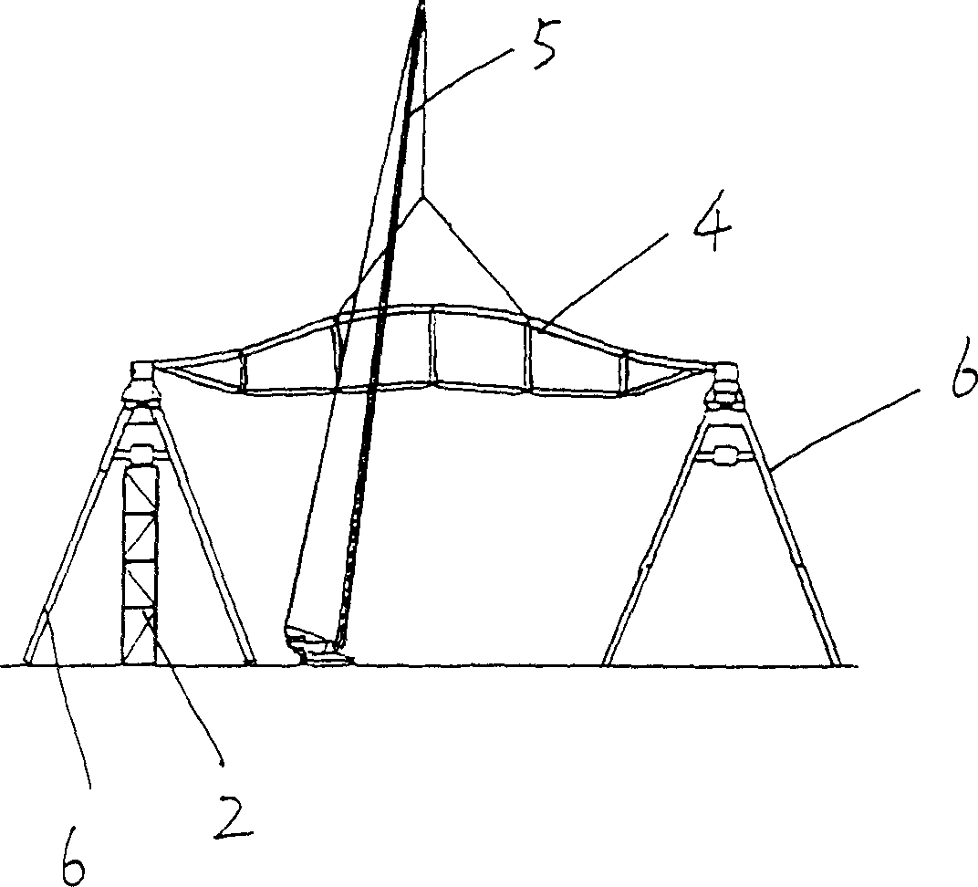
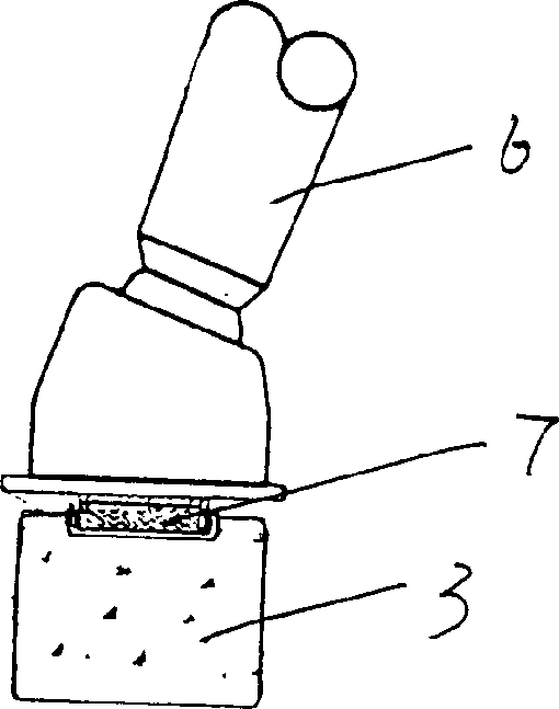
[0010] In Figures 1, 2, 3, 4, and 5, a flat tire frame 1 and a vertical tire frame 2 are arranged on a span end of the space steel structure installation position, and a slideway 3 is arranged on the vertical column position of the space steel structure. Assemble the first main truss 4 on the flat tire frame 1, hoist the first main truss 4 to the vertical tire frame 2 with the crane 5 to assemble the first main truss 4 and the column 6, and install anti-friction blocks at the bottom of the column 6 7. Simultaneously install a pushing device (hydraulic jack 10) and a counterforce frame 8 at the bottom of the column 6, and the counterforce frame 8 is inserted into the support position 9, thereby forming a steel structure jacking matrix. The structure of integrating the first main truss 4 and the column 6 is pushed and translated by the pusher along the slideway 3 by a column distance, and then the second tire frame 1 and the vertical tire frame 2 are assembled at the end of the s...


PUM


Abstract

This invention relates to a matrix type pushing installation method of big span, big depth space steel structure. Its feature is that flat pack moulding bed and stand pack moulding bed are set on one span end at space steel structure installation position; slideway is set at column position of space steel structure. Chief frame is tinetoyed on flat pack noulding bed, chief frame and column is installed by the chief frame is hooked to stand pack moulding bed, then the chief frame and column is pushed translating one column distant along the slideway by pushing equipment. Next frame and column is tinetoyed at span end position, and then secong frame and purlin between two pins are installed. The two pins chief frame and column is pushed translating one column distant along the slideway by pushing equipment. Then above process is repeated until tinetoy is over, finally the whole steel structure is pushed in place along slideway and corrected and fixed. The advantage of this invention is that when construction site and equipment is restricted, structure vibration and deformation can be avoided, cumulative translation matrix form pushing method is used to install big span big depth space steel structure.

Description

technical field [0001] The invention relates to a matrix push installation method for a steel structure in a large-span and large-depth space. Background technique [0002] At present, super-large overall steel structure buildings are widely used. Some existing steel structures with large spaces are generally lifted on site, installed at high altitude, and gradually complete the overall structure installation. However, when encountering various conditions on the construction site Due to the limitation, it is impossible to install the tire frame and the layout of the crane as required on the construction site, especially the limitation of the maximum lifting capacity and lifting moment of the crane. There are some difficult problems in the installation of large-scale space steel structures with large spans. If the installation is located at a high altitude, the structure itself has low stiffness, and the structure has multiple degrees of freedom and structural stability durin...

Claims


Application Information

Patent Timeline
IPC IPC(8): E04B1/35
Inventor 吴欣之王云飞朱伟新陈晓明许勇袁鼎应建华倪洪革
Owner SHANGHAI MECHANIZED CONSTR GRP
Learn More