Concrete member manufacturing molding box

A technology for concrete and components, applied in the field of manufacturing track slabs, concrete sleepers or trapezoidal sleepers, can solve the problems of difficult demoulding, unable to change the position of the sleeper shoulder, damage to the box, etc., and achieve high-efficiency demoulding and simple washing. Effect

Inactive Publication Date: 2005-09-21
NIPPON KOGEN KONKURIITO
View PDF1 Cites 1 Cited by
  • Summary
  • Abstract
  • Description
  • Claims
  • Application Information

AI Technical Summary

Problems solved by technology

[0005] However, the concrete put into the mold box is particularly easy to adhere to the small hole at the bottom of the mold box. Therefore, when the number of shoulders is small, even if the concrete is attached around the small hole, there is no special problem in demoulding. The number of pillow shoulders corresponds to the number of small holes. When the number of small holes increases, the peripheral parts of each small hole are not easy to demould due to the adhesion of concrete
[0006] Moreover, there is also the problem that the peripheral portion of the small hole hits the pillow shoulder during demoulding, and the mold box is damaged.
In addition, since the position of the pillow shoulder is determined by the position of the small hole set at the bottom of the mold box, the position of the pillow shoulder cannot be changed, which is also a problem

Method used


Image

  • Concrete member manufacturing molding box
  • Concrete member manufacturing molding box
  • Concrete member manufacturing molding box

Examples


Embodiment Construction

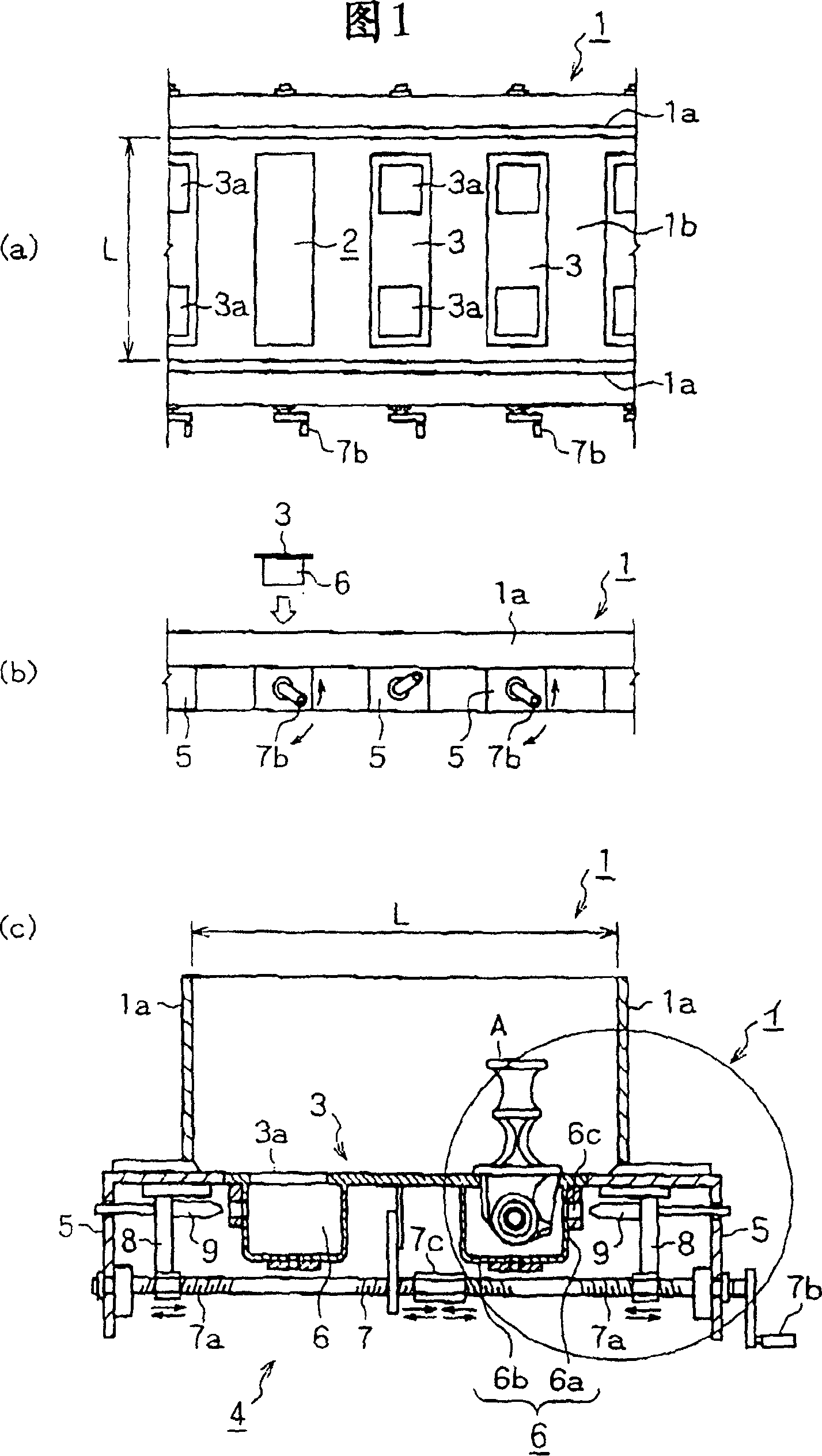
[0026] Figure 1~ Figure 4 An example of a ladder-shaped sleeper molding box (hereinafter referred to as "box") is shown. In the figure, the box main body 1 opens directly above and forms a long and thin box in one direction (for example, the left and right directions in Fig. 1(a)) In particular, the side plate portions 1a and 1a on both sides are installed so that they can slide freely in the out-of-plane direction (for example, the up-and-down direction in FIG.

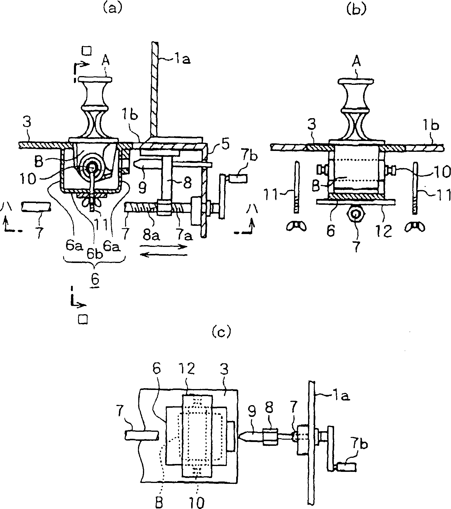
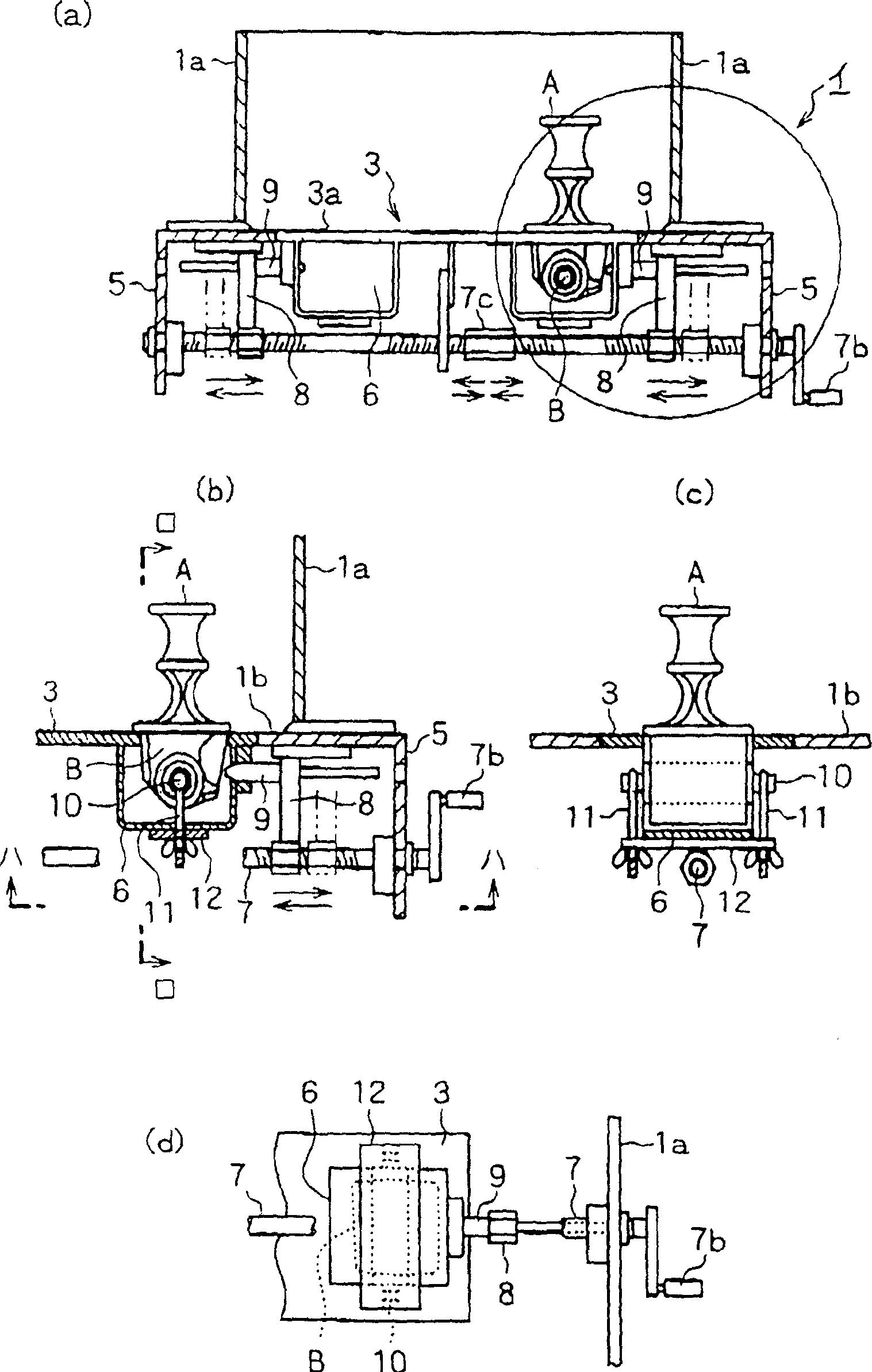
[0027] In addition, in the bottom plate portion 1b of the molded box main body 1, there are predetermined intervals in the longitudinal direction of the side plate portion 1a (for example, the left and right direction in FIG. The rectangular opening 2 is elongated in the outward direction), and the bottom-shaped box 3 is detachably fixed to each opening 2 by the holding mechanism 4 provided on the lower side of the bottom plate 1b.

[0028] In addition, leg portions 5, 5 are vertically provided on both sides of the...


PUM


Abstract

Provided is a form for production of a concrete member which can easily be separated from the form without damaging it even when producing a concrete sleeper having numerous shoulders. This form is composed of a form body 1 having the openings 2 on its bottom, the bottom forms 3 detachably installed in the openings 2, and a holding mechanism 4 for releasably fixing the bottom forms 3 to the lower side of the form body 1. The bottom form 3 has a small hole necessary for setting up an anchor member A to the inside of the form body 1 in reversion. The holding mechanism 4 is composed of the rotary rods 7 bridging horizontally between the legs 5 and 5, the movable rods 8 installed vertically between respective receivers 6 and the legs 5, and the holding pins 9 set up horizontally on the upper ends of the movable rods 8.

Description

technical field [0001] The present invention relates to a concrete member manufacturing form box in which concrete is poured into a form box and a concrete member protruding from the upper side is provided with an anchor (anka-) part in the reverse direction. Concrete sleepers or ladder-type sleepers for components (hereinafter referred to as "shoulders"), which are then used to manufacture track slabs (スラブ). Background technique [0002] As sleepers, for example respectively as Figure 5 ~ Figure 7 Shown, the concrete sleepers 22 ( Figure 5 ) or ladder sleepers 23 ( Image 6 (a), (b)), and then track slab 24 ( Figure 7 ) is well known, the pillow shoulder 21 in this case, when pouring concrete into the mold box that is turned over and placed horizontally, at the bottom of the mold box, only the head of the pillow shoulder 21 is protruded toward the lower side of the mold box, and Temporarily fix it in an upside-down state, and then assemble it into one body by hardenin...

Claims


Application Information

Patent Timeline
Patent Type & Authority Applications(China)
IPC IPC(8): B28B7/00B28B7/10B28B7/26B28B7/38B28B23/00B28B23/18
Inventor 饭泉章久保田浩之
Owner NIPPON KOGEN KONKURIITO
Why Eureka
Try Eureka