Air valve swinging arm shaft with oil pressure unloading plane

A valve rocker arm, rocker arm shaft technology, used in engine components, machines/engines, mechanical equipment, etc.

Active Publication Date: 2005-08-03
CHONGQING ZONGSHEN ENGINE MFG
View PDF0 Cites 5 Cited by
  • Summary
  • Abstract
  • Description
  • Claims
  • Application Information

AI Technical Summary

Problems solved by technology

[0005] Therefore, the present invention solves the lubrication problem between the valve rocker arm and the rocker arm shaft through the lubricating oil passage, and can incr...

Method used


Image

  • Air valve swinging arm shaft with oil pressure unloading plane
  • Air valve swinging arm shaft with oil pressure unloading plane
  • Air valve swinging arm shaft with oil pressure unloading plane

Examples


Embodiment Construction

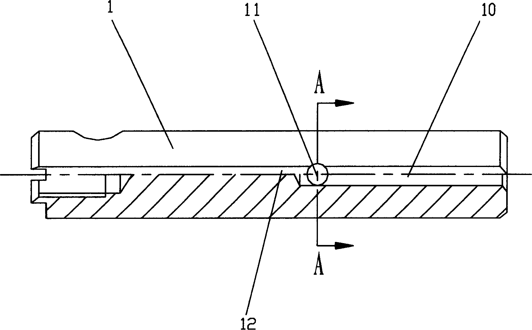
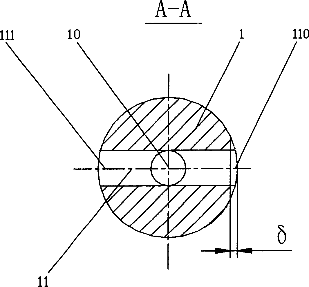
[0010] Such as figure 1 and figure 2 As shown, it is a side view of the rocker shaft of the present invention and a sectional view of the rocker shaft along the A-A direction. The rocker shaft 1 has an axial oil passage 10 along the central axis and a radial oil passage along the radial direction of the rocker shaft. The two ends of the radial oil passage 11 are radial oil passage openings 110, 111, the axial oil passage 10 and the radial oil passage 11 are connected, and the outer surface of the rocker arm shaft 1 has an oil pressure unloading plane 12. The oil pressure unloading plane 12 passes through the radial oil passage port 110 . The purpose of the oil pressure unloading plane 12 is to carry out oil pressure unloading, improve the flow rate of lubricating oil, and lower the temperature. Another radial oil passage port 111 does not offer an unloading plane to enhance the lubricating effect.

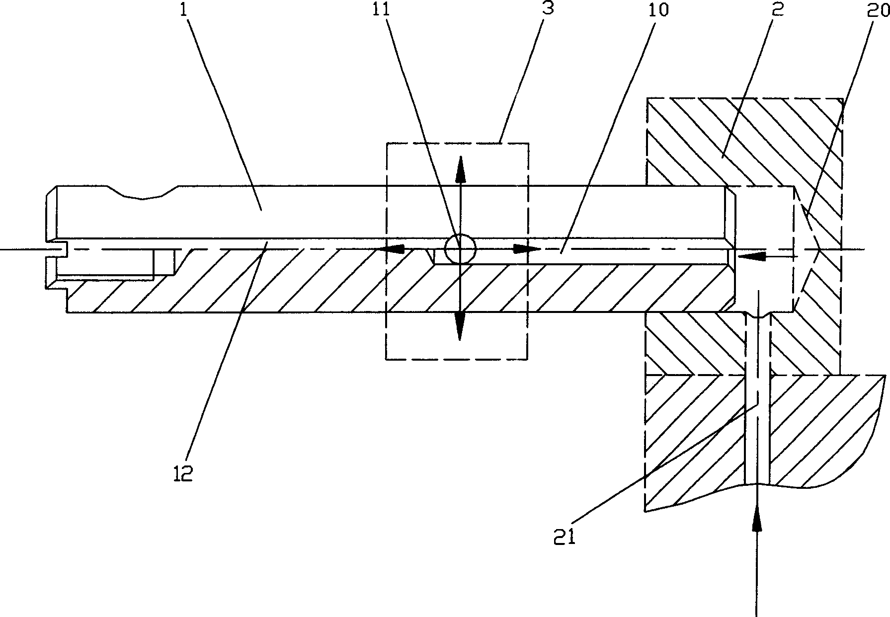
[0011] Such as image 3 Shown is the working schematic diagram of the pres...


PUM


Abstract

The rockshaft with oil pressure unloading plane has one axial oil path along the central axis and one radial oil path along the rockshaft, the axial oil path is connected to the radial oil path, and the outer surface of the rockshaft has one oil pressure unloading plane through the said radial oil path port. Therefore, the present invention solves the problem of lubricating the air valve rock arm and the rockshaft, the oil pressure unloading plane can raise lubricant oil flow speed to reach the aim of lowering the temperature of air valve rock arm and rockshaft.

Description

technical field [0001] The invention relates to a valve rocker shaft with an oil pressure unloading plane, in particular to a valve rocker shaft with an oil pressure unloading plane for motorcycle engine valves. Background technique [0002] The motorcycle engine valve rocker arm and rocker shaft often rub against each other during work, so the wear is very serious and the temperature is very high, which will affect the reliability and service life of both. The current solution is to design a lubricating oil passage between the valve rocker arm and the rocker arm shaft, but since most of the oil volume is to the crank connecting rod, the oil volume to the rocker arm and rocker arm shaft is less and the oil pressure Low, and it is easy to cause the lubricating oil to stay between the rocker arm and the rocker shaft for a long time, causing the temperature to be too high to deteriorate the lubricating oil, resulting in poor lubrication and cooling effects. Contents of the in...

Claims


Application Information

Patent Timeline
IPC IPC(8): F01L1/18
Inventor 刘国伟聂颖
Owner CHONGQING ZONGSHEN ENGINE MFG
Why Eureka
Try Eureka