
A non-contacting tonometer

A non-contact, tonometer technology, applied in the field of quantitative devices, can solve the problems of lack of absolute value and insufficient accuracy of measurement results, and achieve the effect of eliminating dependence, reducing technical training level, and accurate results

Inactive Publication Date: 2005-07-20
ERIC TECH CORP
View PDF6 Cites 4 Cited by
  • Summary
  • Abstract
  • Description
  • Claims
  • Application Information

AI Technical Summary

Problems solved by technology

This indirect method is usually limited by two things: insufficient precision of the measurement results and / or lack of absolute values

Method used


Image

  • A non-contacting tonometer
  • A non-contacting tonometer
  • A non-contacting tonometer

Examples


Embodiment

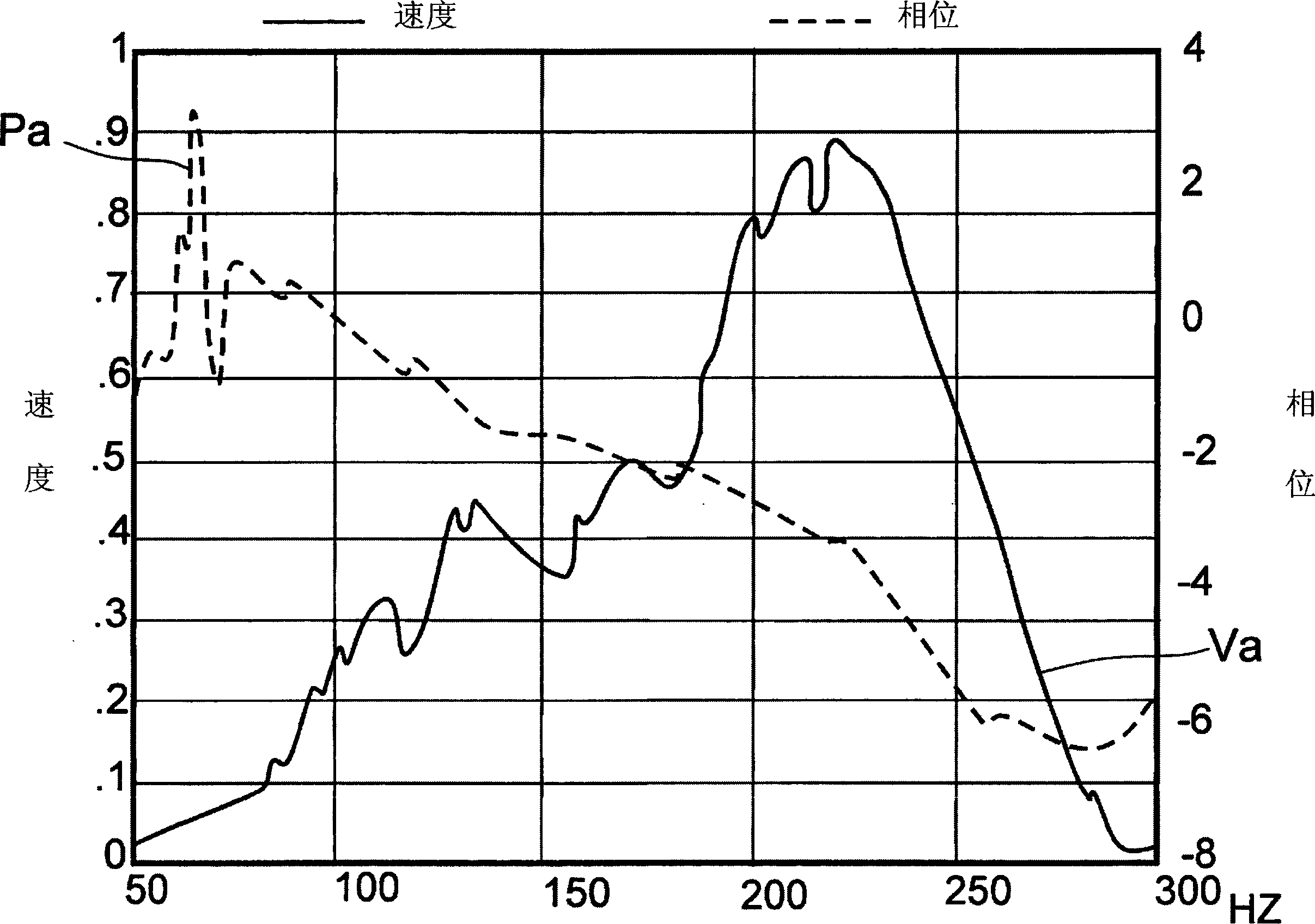
[0052] refer to Figure 3a and 3b , showing velocity, phase lag, and one or more resonance points measured from low-IOP and high-IOP pig eyes, respectively. In this example, a measured pressure representing IOP is applied to the eye with an intrusive fluid connection. Acoustic energy is applied using a frequency oscillator in the 50 to 300 Hz range to induce vibrations in the eye. The preferred frequency range is used to help identify uncertain resonance points. A laser velocimeter is applied to the surface of the eye in order to measure the vibratory response of the eye surface, ie velocity.

[0053] refer to Figure 3a , curve Va represents the vibration velocity response of the low-IOP eye stimulated by sound. Note that the maximum velocity inflection point in curve Va occurs at greater than 220 Hz, indicating resonance. Curve Pa represents the phase lag between the excitation energy and the oscillations of the low IOP eye 1 . At these low IOPs, the eyes exhibit grea...


PUM


Abstract

The invention relates to apparatus and method for measuring Internal Ocular Pressure (IOP) comprises applying a perturbing vibration (2) into an eye (1) over a range of frequencies. A vibrational response of the surface of the eye is measured such as by using a laser velocimeter (6), said response including velocity and rate of change of the phase lag. Further, geometric properties such as volume of the eye are measured such as by using as a laser interferometer (13) to measure characteristics such as the eye's axial length and cornea thickness. Use of multiple characteristics normalize the effect of an eye's mechanical and geometric properties and thereby more accurately determine the IOP.

Description

field of invention [0001] The present invention relates to a non-contact device and method for obtaining physical, physiological and structural properties of the eyeball, in particular for measuring the amount of intraocular pressure in the eye. In particular, vibrations are induced in the eye, and a laser velocimeter and a laser interferometer are applied. Background of the invention [0002] Measuring the eye Intraocular pressure (IOP) is a measurement of the fluid pressure inside the eyeball. Detection of IOP is beneficial because it is an indicator of eye health. Excessively high IOP has been linked to optic nerve damage, such as glaucoma. [0003] Think of the eyeball as an elastic container filled with a fluid that has incompressible properties. One can compare such an elastic container to a balloon with stretchable walls, where the increase in liquid volume causes a change in internal pressure, which is balanced by expansion of the container walls. Fluid inside th...

Claims


Application Information

Patent Timeline
Patent Type & Authority Applications(China)
IPC IPC(8): A61B3/10A61B3/16
CPCA61B3/165A61B3/1005
Inventor 奥斯卡·库扎尼安德鲁·J.·巴克唐纳德·E.·詹姆斯
Owner ERIC TECH CORP
Learn More