
Balance system for single cylinder engine

A technology for balancing systems, balancing components, applied in the direction of machines/engines, counterweights, mechanical equipment, etc., can solve problems such as increased cost and complexity

Inactive Publication Date: 2005-05-18
KOHLER CO
View PDF1 Cites 6 Cited by
  • Summary
  • Abstract
  • Description
  • Claims
  • Application Information

AI Technical Summary

Problems solved by technology

Therefore, the cost and complexity associated with designing and manufacturing such an engine will increase

Method used


Image

  • Balance system for single cylinder engine
  • Balance system for single cylinder engine
  • Balance system for single cylinder engine

Examples


Embodiment Construction

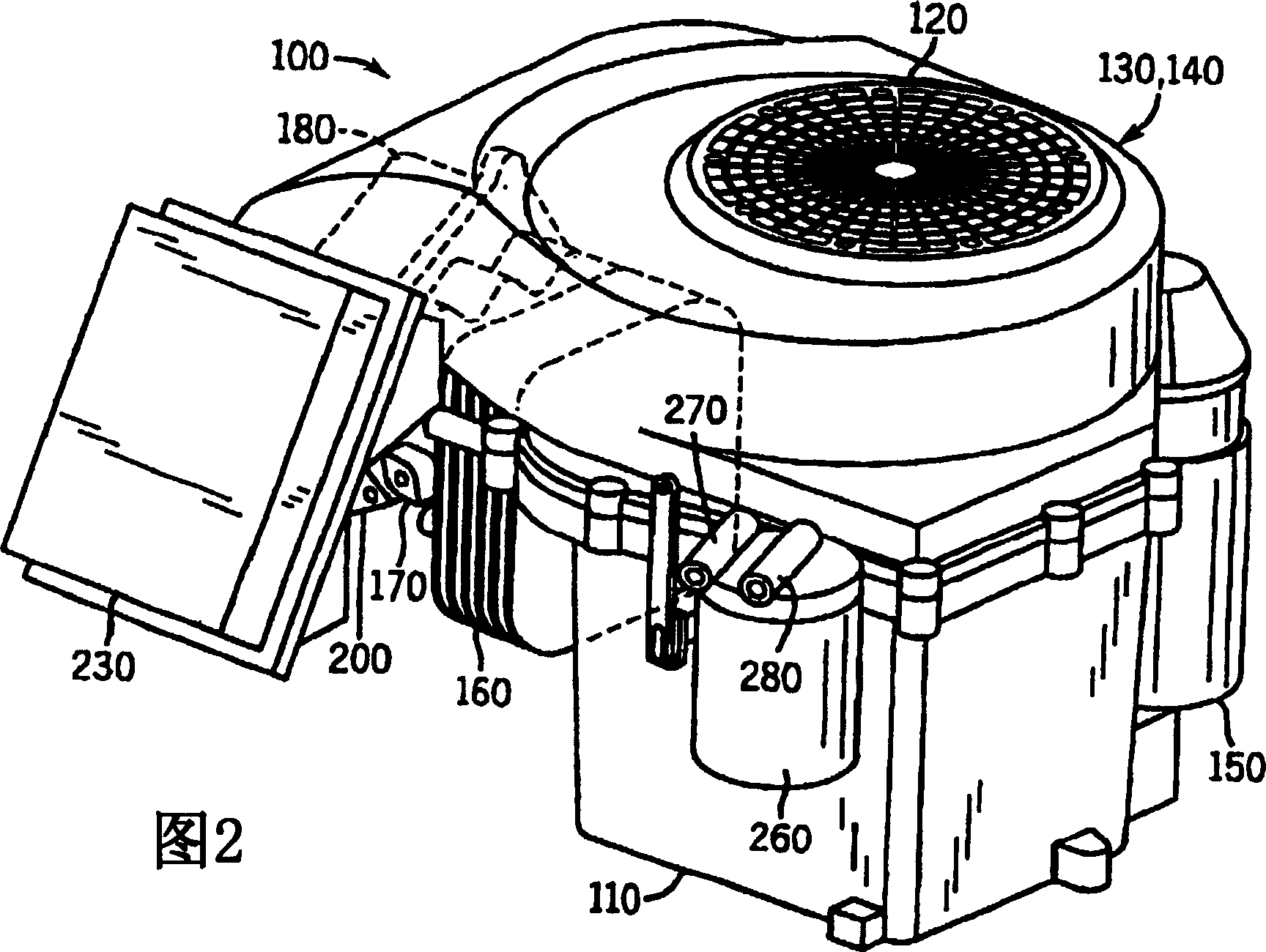
[0029] Referring to FIGS. 1 and 2 , a novel single-cylinder four-stroke internal combustion engine 100 designed by Kohler Co. of Kohler, Wisconsin includes a crankcase 110 and a fan case 120 with a fan 130 and a flywheel 140 inside the fan case 120 . The engine 100 also includes a starter 150 , a cylinder 160 , a cylinder head 170 and a rocker cover 180 . The exhaust port 190 illustrated in FIG. 1 and the intake port 200 illustrated in FIG. 2 are connected to the cylinder head 170 . As is well known in the art, during operation of engine 100 , piston 210 (see FIG. 7 ) moves back and forth within cylinder 160 , towards and away from cylinder head 170 . Movement of the piston 210 thereby causes rotation of the crankshaft 220 (see FIG. 7 ), as well as rotation of the fan 130 and flywheel 140 connected to the crankshaft. Rotation of fan 130 cools the engine and rotation of flywheel 140 maintains a relatively constant rotational momentum.

[0030]Referring specifically to FIG. 2 ...


PUM


Abstract

A balancing system (500) and method for balancing piston forces of a single cylinder internal combustion engine (100) are disclosed. The balance system (500) includes a crankshaft (220), a balance assembly (445) and a groove (610). The crankshaft (220) includes a crankshaft portion (510), a crank (530), a crank pin (520), and an eccentric flange (550) adjacent the crank (530). The balance assembly (445) has a balance mass portion (570) and a coupling arm (580) secured to each other, and a pin (600) protruding from the side of the balance mass portion (570). Eccentric flange (550) supports coupling arm (580). The groove (610) can accommodate the pin (600) and the pin (600) can slide along the groove (610) and also rotate within the groove (610) so that the balance assembly (445) moves towards and away from the crankshaft ( 220) can be rotated.

Description

technical field [0001] The present invention relates to single cylinder internal combustion engines such as those used to power lawnmowers, sump pumps, portable generators and other equipment. In particular, the present invention relates to a balancing system within such an engine that eliminates or reduces engine vibrations generated by the reciprocating motion of the pistons within the engine. Background technique [0002] The main cause of vibration in a single cylinder engine is the reciprocating motion of the piston. The piston starts and stops twice during each revolution of the crankshaft, and the reaction of forces accelerating and decelerating the piston is imposed on the engine block as vibrations in a direction generally parallel to the piston axis. When operating in equipment such as a lawn mower, the vibration energy generated by the engine is transmitted through the equipment to the operator. This vibration is uncomfortable and can cause operator fatigue. Ev...

Claims


Application Information

Patent Timeline
Patent Type & Authority Applications(China)
IPC IPC(8): F02B75/00F02B75/16F16F15/26F16F15/28
CPCF02B75/007F02B75/16F16F15/26F16F15/283Y10T74/2183
Inventor T·M·罗特W·D·柯尼希斯
Owner KOHLER CO
Learn More