Eletronic card connector

A technology for electronic cards and connectors, which is applied to instruments, electrical components, inductive record carriers, etc., and can solve the problems of shortening length, small size of electronic card connectors, and inability to effectively reduce the volume.

Inactive Publication Date: 2005-03-30
MOLEX INC
View PDF0 Cites 0 Cited by
  • Summary
  • Abstract
  • Description
  • Claims
  • Application Information

AI Technical Summary

Problems solved by technology

[0010] 1. The length of the first terminal 1 is too long and cannot be effectively shortened, resulting in the disadvantage of occupying the space of the electronic card connector: the length of the conventional first terminal 1 includes the elastic arm 12 connected end to end, the arched arm 13 and the tail part 14 are all necessary parts, and it is impossible to omit any part to shorten the length. This problem has been troubled by the industry for a long time, but it has not been effectively solved
[0011] 2. The volume of the entire electronic card connector, or even the entire electronic device, cannot be further reduced: since the length of the first terminal 1 cannot be effectively shortened, the volume of the electronic card connector cannot be made smaller, making it relatively more compact. The electronic device using the conventional electronic card connector also suffers from the problem that the size cannot be effectively reduced, and it cannot meet the requirements of lightness, thinness, shortness, and smallness
[0012] 3. It cannot be prevented from moving in the direction of the insertion space: when the elastic arm 12 of the conventional first terminal 1 moves elastically, due to the elastic movement range from the elastic arm 12 , the arched arm 13 , to the tail 14 Without any stoppers, the elastic arm 12 of the first terminal 1 will have trouble moving in the direction of the insertion space improperly, causing errors

Method used


Image

  • Eletronic card connector
  • Eletronic card connector
  • Eletronic card connector

Examples


Embodiment Construction

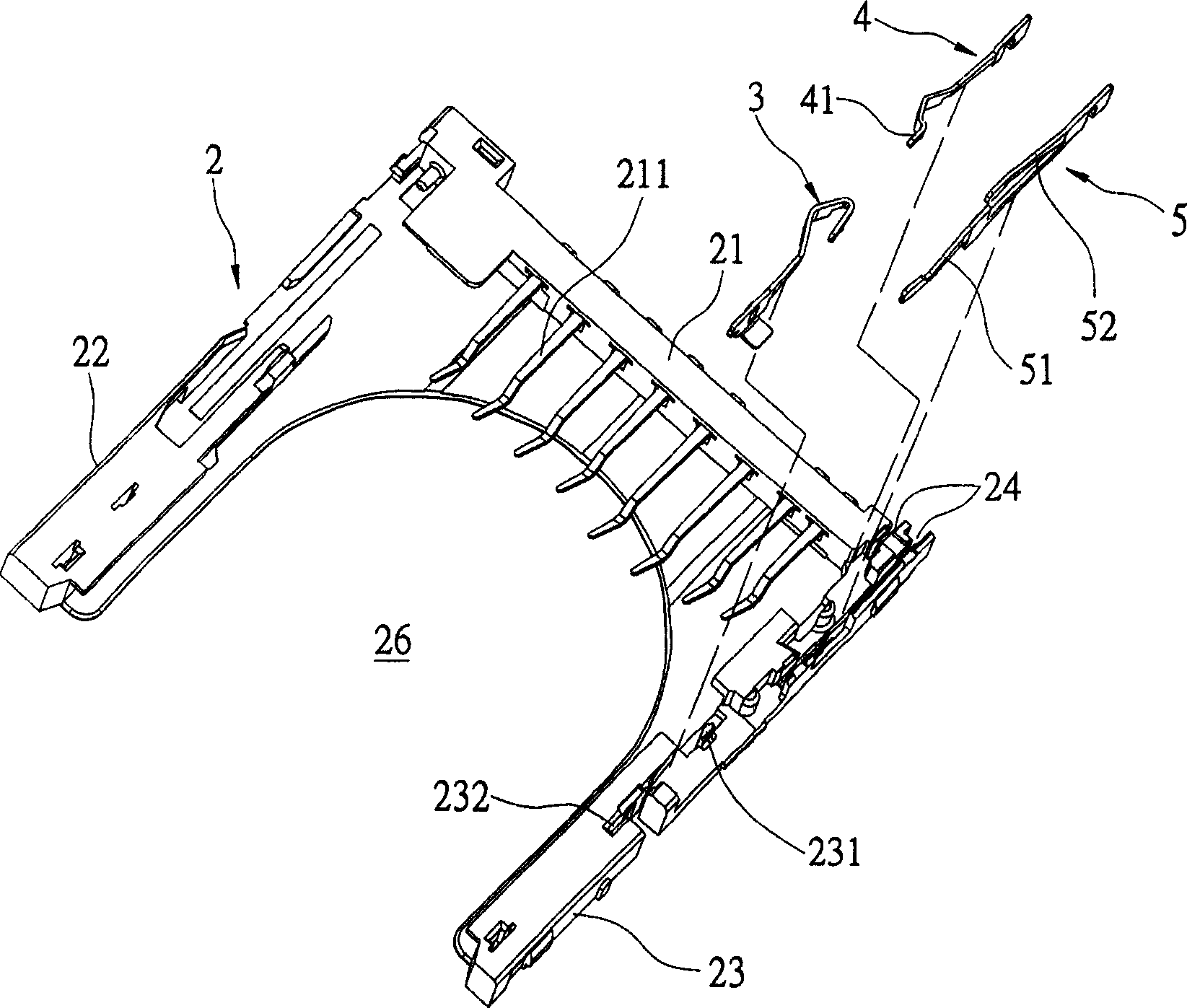
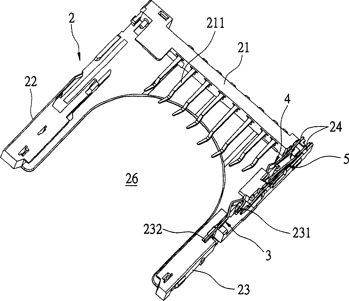
[0022] see Figure 2-6 As shown, the present invention provides an electronic card connector, which can be used for plugging in and withdrawing electronic cards. The electronic card connector includes an insulating body 2, a first terminal 3, a second terminal 4 and a third terminal 5.

[0023] The insulating body 2 has a base body 21 and two left and right side arms 22, 23, and the two side arms 22, 23 are integrally connected to both sides of the base body 21 to form a U-shaped body, so that the base body 21 An insertion space 26 is formed between the two side arms 22, 23, and the insertion space 26 can be used for inserting an electronic card. The base 21 is provided with a plurality of terminal accommodating grooves at intervals for accommodating the conductive terminals 211 . The connection between the right side arm 23 of the insulating body 2 and the base body 21 is provided with two slots 24 for setting the second and third terminals 4 and 5 . The middle of the righ...


PUM


Abstract

The connector includes following parts: insulating body possesses a base body, and left and right side arms; a planting space formed between the base body and the two side arms; stopper is setup on the insulating body; a connector setup on insulating body possesses main body, arched arm, extension arm, elastic arm connected to the main body and front end of the arched arm, and bending part connected to back ends of the arched arm and the extension arm; there are first and second contact parts on outside the arched arm and the extension arm; the stopper is in the space surrounded by the arched arm, bending part and the extension arm in order to stop the connector to move towards to the planting space. Another connector possessing a contacting part is setup on the insulating body. When electronic card is inserted into the planting space, lateral margin of the card pushes first contact part of the connector so that second contact part touches the contact part of another connector.

Description

technical field [0001] The present invention relates to an electronic card connector, in particular to an electronic card connector that can be inserted into an electronic card so that the electronic card can be electrically connected to a circuit structure or a storage device. Background technique [0002] Press, the electronic card (IC card) is a data input device, which can be electrically connected to a circuit structure or a storage device, such as a word processor, personal computer or other circuit structure, and the data stored in the electronic card will be transmitted To this circuit structure, the electronic card is a portable tool that can be easily inserted and ejected by an electronic card connector. [0003] The known electronic card connector can be used to plug in and withdraw from the electronic card, and it mainly includes an insulating body, a first terminal for detection (commonly referred to as a detection terminal), and a second terminal for write prot...

Claims


Application Information

Patent Timeline
IPC IPC(8): G06K7/06G06K17/00H01R12/24H01R12/38
Inventor 张家祯
Owner MOLEX INC
Why Eureka
Try Eureka