Soft switch power factor correcting circuit

A power factor correction, soft switching technology, applied in the output power conversion device, the conversion of DC power input to DC power output, electrical components and other directions, can solve the problems of low efficiency and large on-state loss of the whole machine Improved efficiency and reduced on-state loss

Active Publication Date: 2005-03-23
EMERSON NETWORK POWER CO LTD
View PDF0 Cites 3 Cited by
  • Summary
  • Abstract
  • Description
  • Claims
  • Application Information

AI Technical Summary

Problems solved by technology

[0006] The invention overcomes the shortcomings of large on-state loss and low efficiency of the whole machine in the prior art by adding a buffer network and auxiliary power switch on the basis of the above-mentioned low on-state loss hard switching power factor correction circuit

Method used


Image

  • Soft switch power factor correcting circuit
  • Soft switch power factor correcting circuit
  • Soft switch power factor correcting circuit

Examples


Embodiment Construction

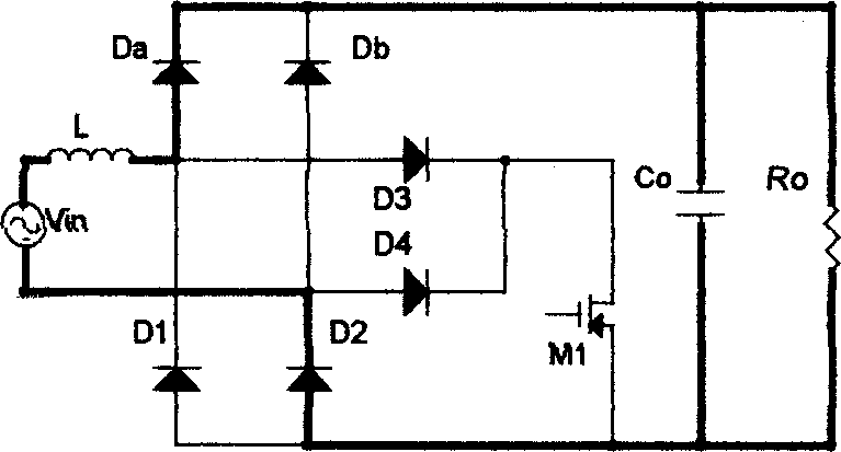
[0018] The inventive circuit such as image 3 As shown, it includes a diode bridge rectifier circuit and a boost converter circuit, and the bridge rectifier circuit includes a first diode D1, a second diode D2, a third diode D3, a fourth diode D4 four rectifier diodes, the common cathode of the bridge rectifier circuit is connected to the drain of the main power switch M1, and its common anode is connected to the source of the main power switch M1, and the input AC power V in One end of the series branch composed of the filter inductance L is connected to the anode of the eighth diode Da between the first diode D1 and the third diode D3, and the other end is connected to the anode of the ninth diode Db. Between the second diode D2 and the fourth diode D4, the cathodes of the eighth diode Da and the ninth diode Db are connected to the output filter capacitor C o One end, the output filter capacitor C o The other end is connected to the common anode of the bridge rectifier cir...


PUM


Abstract

A flexible switch power factor correcting circuit includes commutation bridge circuit and voltage boosting convertor. The voltage boosting convertor includes the buffer network and assistant power switch. The seventh diode connects with the two ends of the main power switch in series reversely. The resonant capacitance connects with the two ends of the main power switch parallelly. One end of the resonant inductance connects with the common cathode of the commutation bridge circuit and its other end connects with the anode of the fifth diode. The cathode of the fifth diode connects with the anode of the sixth diode. The cathode of the sixth diode connects with the anode of the tenth diode. The cathode of the tenth diode connects with one end of the filtering capacitance. One end of the buffer capacitance connects with the common cathode of the commutation bridge circuit and its other end connects with the anode of the tenth diode. The drain electrode of the assistant power switch connects with the anode of the sixth diode and its source electrode connects with the common anode of the commutation bridge circuit. When the power tube of the voltage boosting convertor is shut off, in the circuit only two semiconductor devices have pressure drop, the main switch is the zero voltage transforming flexible switch and it increases the working efficiency of the circuit.

Description

technical field [0001] The invention relates to a power factor correction circuit, in particular to a soft switching power factor correction circuit with low loss and zero voltage conversion. Background technique [0002] At present, a general power factor correction circuit is composed of a front-stage diode bridge rectifier circuit and a post-stage boost converter. In order to reduce the size and weight of the whole machine, it is generally realized by increasing the switching frequency of the boost converter. However, as the frequency increases, the loss of the power switch increases, resulting in a decrease in overall machine efficiency. The typical topology of zero voltage transition (ZVT) is a zero voltage transition (ZVT) soft switching circuit that realizes zero voltage (ZVS) turn-on of the power switch and improves the working conditions of the reverse recovery diode by adding a resonant network. However, the main disadvantage of this circuit is that no matter whe...

Claims


Application Information

Patent Timeline
Patent Type & Authority Applications(China)
IPC IPC(8): H02M3/00
CPCY02B70/1491Y02B70/10Y02P80/10
Inventor 史立生
Owner EMERSON NETWORK POWER CO LTD
Why Eureka
Try Eureka