Magnetron cathode assembly

A magnetron cathode and component technology, which is applied to the cathode of magnetron, multi-cavity magnetron, and time-of-flight electron tube, and can solve the problems of poor precision and other problems

Inactive Publication Date: 2005-03-23
PANASONIC CORP
View PDF1 Cites 7 Cited by
  • Summary
  • Abstract
  • Description
  • Claims
  • Application Information

AI Technical Summary

Problems solved by technology

Then the problem arises again, the accuracy of preventing the rotation of the outer terminals 31, 32 from getting worse

Method used


Image

  • Magnetron cathode assembly
  • Magnetron cathode assembly
  • Magnetron cathode assembly

Examples


Embodiment Construction

[0041] Preferred embodiments of the magnetron cathode assembly according to the present invention will be described in detail below with reference to the accompanying drawings.

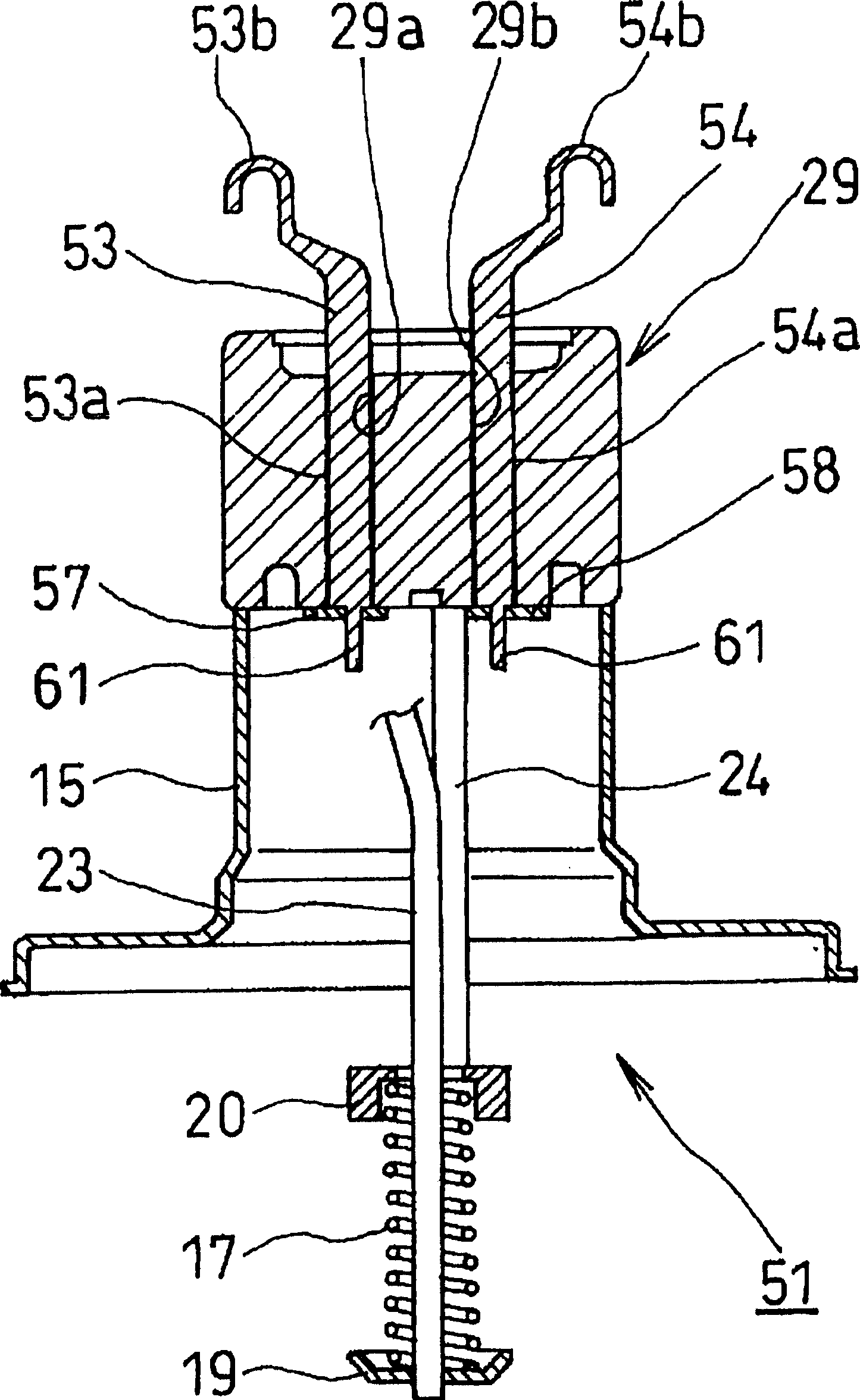
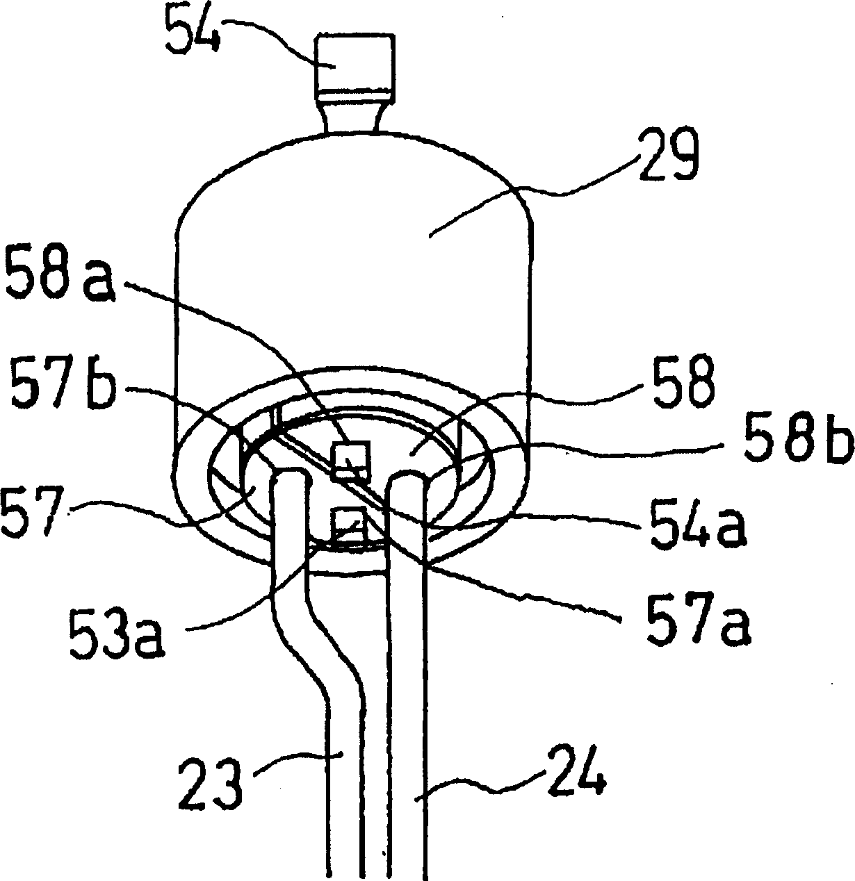
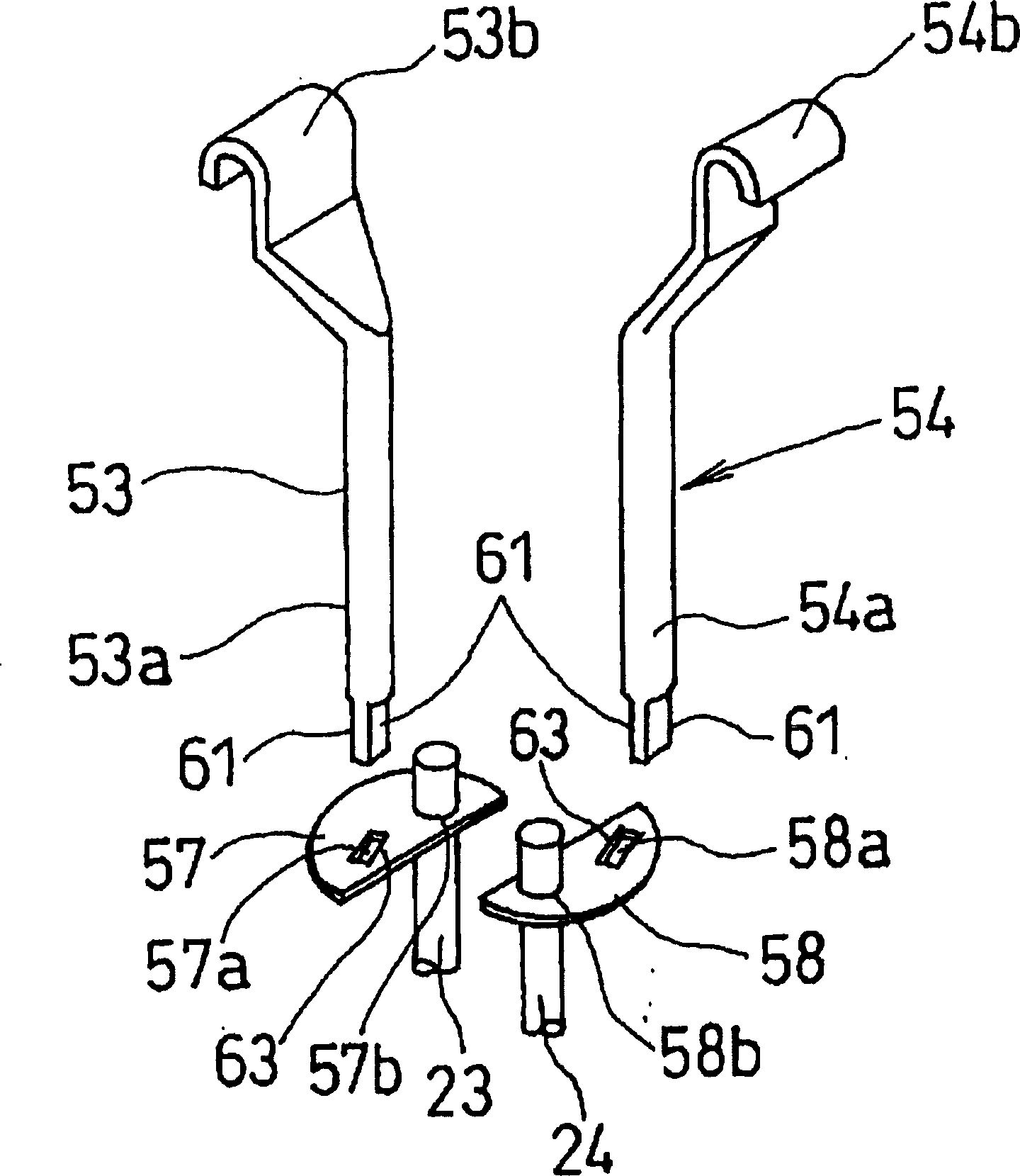
[0042] figure 1 One embodiment of a magnetron cathode assembly according to the invention is shown.

[0043] The magnetron cathode assembly 51 in this embodiment is used for magnetrons employed in microwave heating equipment such as electric ovens. The magnetron cathode assembly 51 comprises: a metal tube 15 joined to the open end edge of the anode block, coaxial with the anode block and forming part of a vacuum vessel; a coil-shaped cathode 17 arranged on the axis of the cathode block Part; a pair of cathode terminal leads 23 and 24, which support the cathode 17 through end caps 19 and 20, which are bonded to the leading ends of the cathode 17; a rod insulator 29, which is hermetically bonded to the metal tube 15, and has a pair of through holes 29a and 29b passing through the rod insulator 29 alo...


PUM


Abstract

A magnetron cathode assembly which realizes stopping of turn of an external terminal inserted into a stem insulator without increasing a manufacturing cost. A leading end of a base end axial portion of an external terminal has a non-circular section by providing a flat surface in at least one position on its peripheral surface, and a straight stop edge that fits to the flat surface thereby to carry out stopping of turn of the external terminal is provided for a terminal fitting hole of a sealing metal plate into which the leading end of this external terminal is fitted.

Description

technical field [0001] This invention relates to a cathode assembly of a magnetron used in microwave heating equipment such as an electric furnace. Background technique [0002] Magnetrons are used in microwave heating equipment, such as Figure 6 As shown, it generally includes: a vacuum tube 1 located in the central part, a plurality of heat radiation fins 2 arranged around the vacuum tube 1, a pair of ring magnets 3 coaxially installed with the vacuum tube 1, and used to magnetically connect the two rings. A pair of frame yokes 4 of the magnet 3 , and a filter circuit portion 5 . [0003] In addition, the vacuum tube 1 includes: a cylindrical anode 6; a cathode assembly 7 arranged on the axis of the cylindrical anode 6; a plurality of sheet blades 8 arranged on the inner surface of the cylindrical anode 6 and The central axis of the anode 6 extends radially; a plurality of strip-shaped rings 9 and 10 electrically connect these blades alternately; [0004] The cathode as...

Claims


Application Information

Patent Timeline
Patent Type & Authority Applications(China)
IPC IPC(8): H01J23/14H01J23/05H01J25/587
CPCH01J23/14H01J23/05H01J25/587
Inventor 齐藤悦扶石井健吉原正训大栗秀树塚田敏行
Owner PANASONIC CORP
Why Eureka
Try Eureka