
Clamping device and regulating unit

A clamping device and clamping sleeve technology, which can be applied to fixing devices, fluid pressure actuating devices, mechanical equipment, etc., can solve problems such as damage, device damage, clamping jaws, etc., to improve operational reliability and facilitate elasticity. The effect of features

Inactive Publication Date: 2005-03-16
HERBERT HANCHEN
View PDF2 Cites 7 Cited by
  • Summary
  • Abstract
  • Description
  • Claims
  • Application Information

AI Technical Summary

Problems solved by technology

The disadvantage of this kind of jaw device is that in practical applications, when using the jaws, the force frequently applied often causes the jaws to get stuck, but it is difficult to be released again after the jaws get stuck, which depends on the force generated and absorbed. the force value and if the jamming is severe, it can sometimes lead to damage or even destruction of the device

Method used


Image

  • Clamping device and regulating unit
  • Clamping device and regulating unit
  • Clamping device and regulating unit

Examples


Embodiment Construction

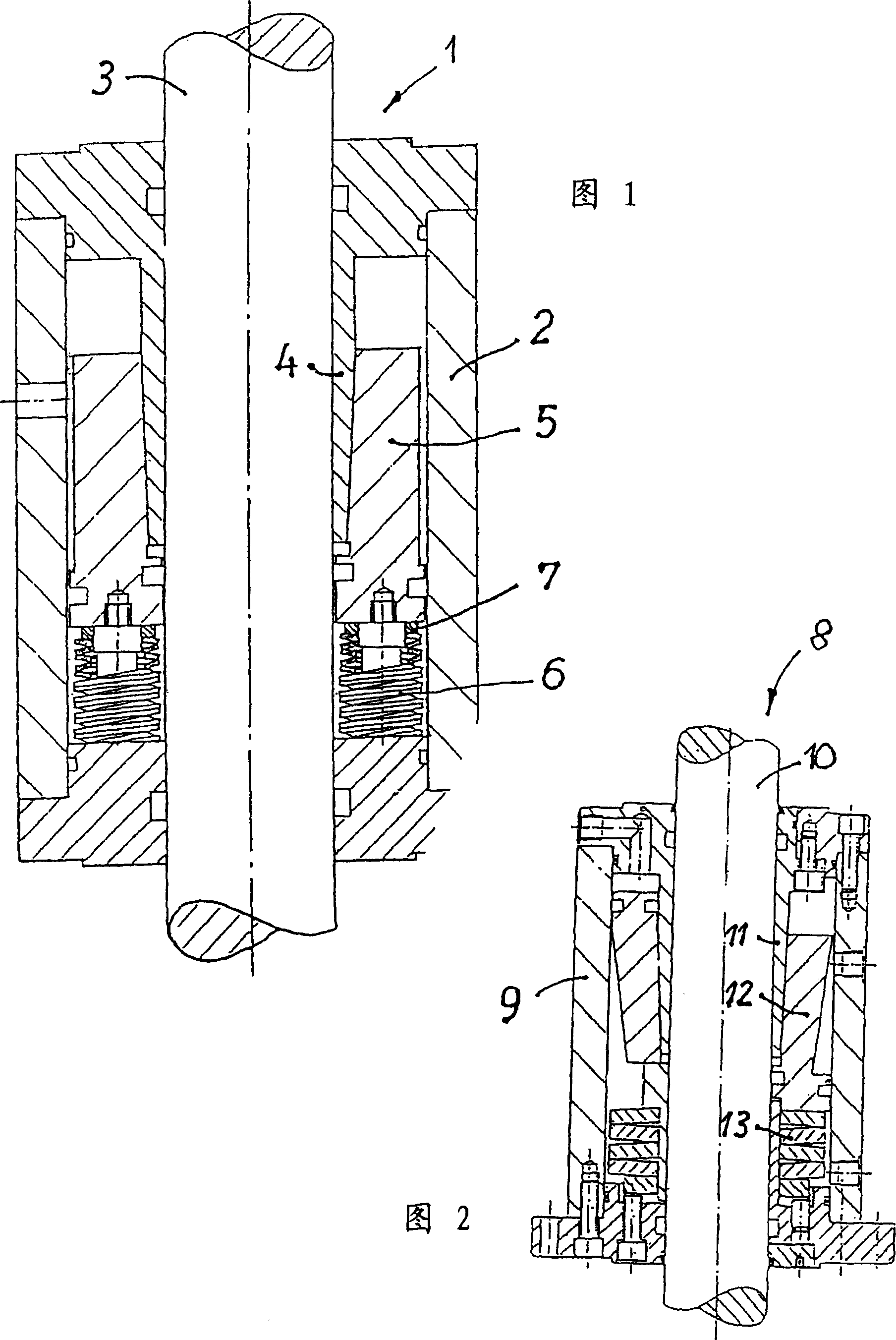
[0036] FIG. 2 shows a clamping device known from the prior art, in particular DE 37 070 46 A1. The known clamping device 8 has a three-part housing, in which a rod 10 can be clamped by means of a clamping sleeve 11 . This clamping takes place by means of a tensioning piston 12 which is provided with a prestressing or biasing force by the action of a coaxially mounted leaf spring unit 13 . The clamping sleeve 11 is released by supplying the tensioning piston 12 with pressure medium, since the force exerted by the pressure medium counteracts the prestressing or biasing force of the elastic unit 13 .

[0037] The leaf spring unit is therefore permanently prestressed in both the clamped and the unclamped position, ie all the leaf springs forming the leaf spring unit are prestressed by the same amount, the prestress being higher in the unclamped position. Since the leaf springs are connected one after the other, in the case of a single layer, each spring applies the total prestres...


PUM


Abstract

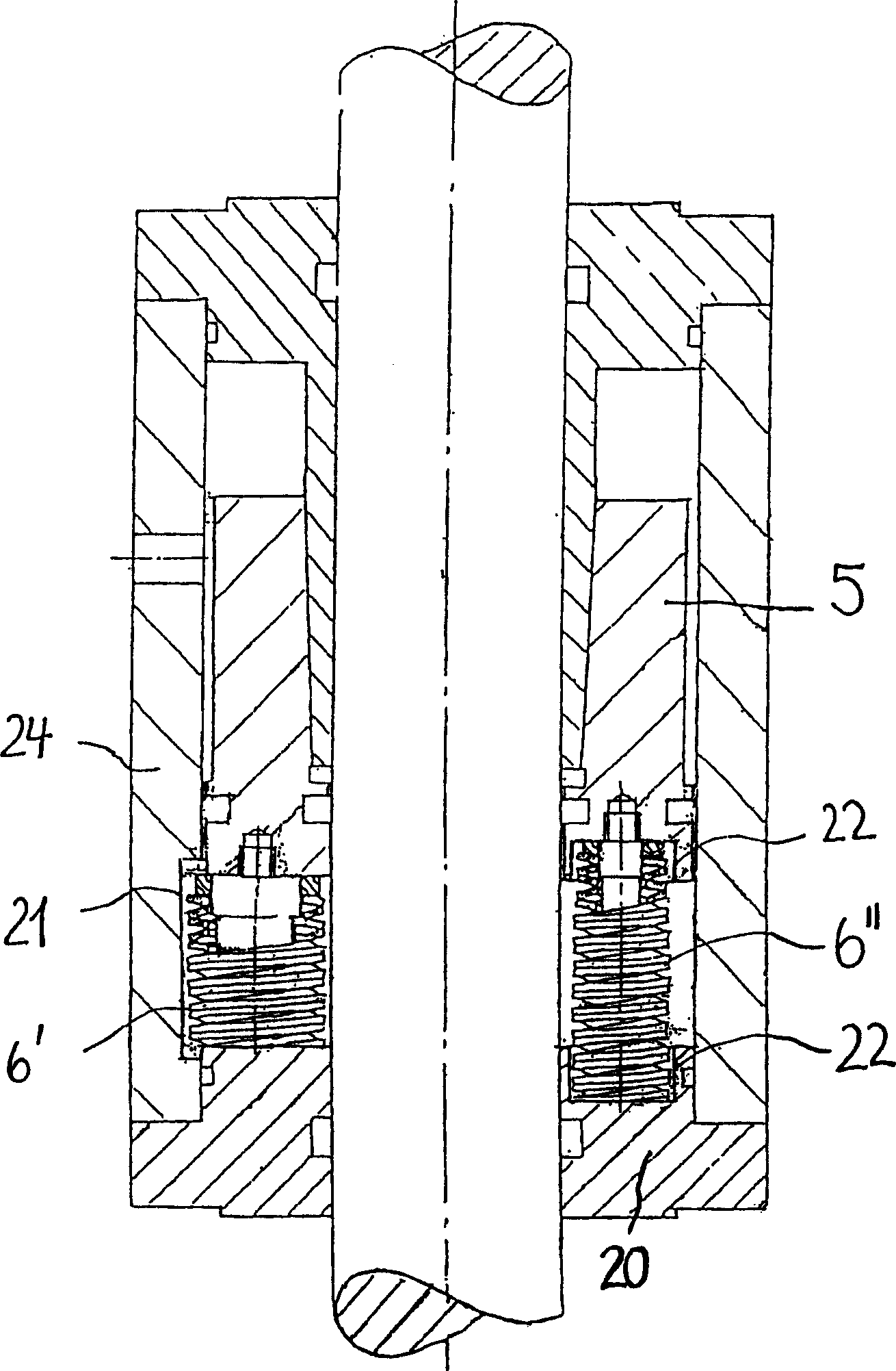
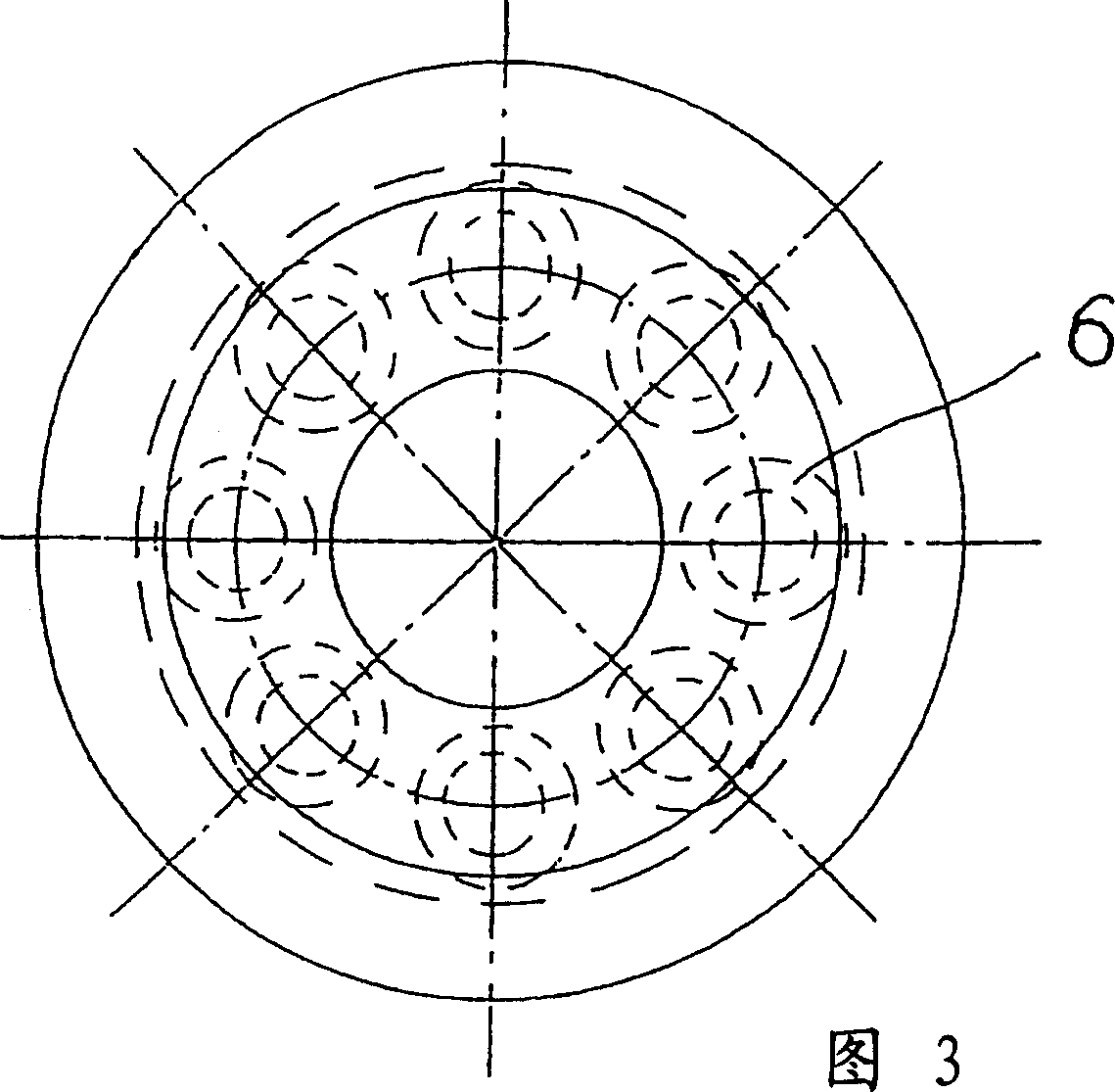
The invention relates to a clamping device for a rod (3) which moves in an axial translatory or rotating manner. Said device comprises a housing (2), a clamping sleeve (4) which is axially fixed in said housing, a tensioning piston (5) which can be displaced in the housing embodied as a cylinder, and a spring device for pre-tensioning the piston (5) in the direction of the clamping sleeve (4) in the locking state. Said spring device is embodied as at least one helical plate spring (6, 6', 6', 19) which, in the event of a fracture, preserves the holding force and the dynamic course of the same. In a first form of embodiment, the at least one helical plate spring (19) is coaxially arranged in relation to the rod (3) to be clamped. In a second form of embodiment, a plurality of helical plate springs (6, 6', 6') are arranged on the circumference of the rod (3) in such a way that they are parallel to the axis thereof, for the distribution of a pre-tensioning force acting on the spring device.

Description

technical field [0001] The invention relates to a clamping device and an adjusting device, in particular a working cylinder with a piston rod, having the features of the preamble of claim 1 . Background technique [0002] Clamping devices for axially movable rods, such as piston rods of working cylinders or stationary shafts, are known. Such a clamping device is known from DE 37 07 046 A1. This clamping device is connected to a movable part or device in relation to the rod to be clamped, and the clamping force is then generated, for example, by means of a tensioning piston with an inner layer and a clamping sleeve with an outer layer . Since the size of the clamping force directly depends on the size of the elastic force, sets of plate springs have been used in the prior art for high retaining force or clamping force, depending on the technical requirements, by Single-layer or multi-layer leaf springs arranged in rows in alternating directions are formed and arranged coax...

Claims


Application Information

Patent Timeline
Patent Type & Authority Applications(China)
IPC IPC(8): F15B15/26F16B1/02
CPCF15B15/262
Inventor 赫伯特·布西
Owner HERBERT HANCHEN
Learn More