
Interferometric method using partial compensation lens to realize nno-spherical surface shape

A technology of interferometric measurement and compensation lens, which is applied in the field of interferometric measurement, can solve the problems of stray light interference, large loss of return light wave, poor quality, etc., and achieve the effect of high precision and good stability

Inactive Publication Date: 2005-03-02
BEIJING INSTITUTE OF TECHNOLOGYGY
View PDF0 Cites 42 Cited by
  • Summary
  • Abstract
  • Description
  • Claims
  • Application Information

AI Technical Summary

Problems solved by technology

The current solution to this problem is to use a holographic element with a spherical lens to compensate the large wave aberration produced by the aspheric surface. The holographic element is manufactured by a numerical control method, which can compensate almost any aspheric surface. However, due to the limitation of its diffraction principle, the transmitted light of the holographic element In addition to the useful measured wave surface, there are also zero-order and high-order sub-wave diffraction light, which makes the measured wave surface have greater stray light interference, interference fringes are not clean, and the quality is poor
In addition, because the diffraction efficiency is not high, and the light is diffracted twice, the loss of the reflected light wave is large

Method used


Image

  • Interferometric method using partial compensation lens to realize nno-spherical surface shape

Examples


Embodiment Construction

[0018] The present invention will be further described below in conjunction with the accompanying drawings and specific embodiments.

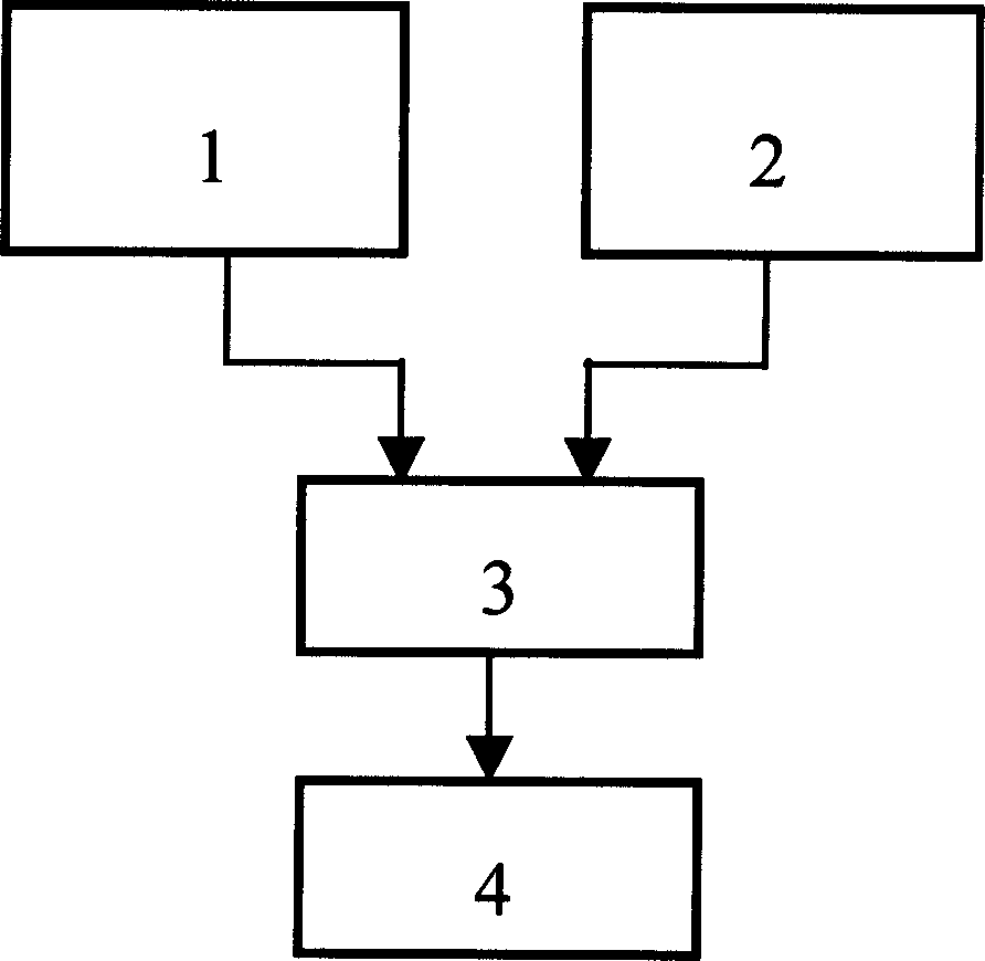
[0019] This method is implemented in the following steps:

[0020] Step 1: Calculate the virtual interference fringes from the optical path of the interferometer, the standard data of the measured aspheric surface and the partially compensated lens structure;

[0021] Step 2: Digital moiré synthesis with the actual interference fringes obtained by the actual interferometer to realize the subtraction of the measured wave front and the theoretical wave front, the systematic error in the interferometer is offset, and the moiré fringes are the interference between the actual aspheric surface and the standard aspheric surface stripe;

[0022] Step 3: Then process the measured aspheric surface shape error by digital phase shifting.

[0023] The invention has the advantage that: the surface shape of the measured aspheric surface is not limited to a ...


PUM


Abstract

A interference measuring method of inspherical face form realized by using partial compensating lens belongs to electrooptical technical field, having no requirement that large aberration wave front of inspherical face form has to be compensated completely by compensating lens, but allowing residual wave difference not larger than fifty wavelengthes exists, changing traditional small wave difference interference measuring system into large wave difference by using digit Mohr phase shift phase shift method. The invention has the structure of compensating lens simplified. The difficulty of design, processing of which decreased and the measuring range of which extended; by using refraction principle, interference fringe is very clean because of no perturbance from other light created by holographic element, and which has little lose; the measuring accuracy is high and stability is good; it can be used to measure varies of rotational symmetric aspheric surface especially for aspheric surface with large relative aperture and convex inaspheric surface with large inaspheric ratio.

Description

Technical field [0001] The invention is an interferometric measurement method for realizing an aspheric surface shape by using a partially compensated lens, which belongs to the field of optoelectronics [0002] technology field. Background technique [0003] Measuring the surface shape of optical components by interferometry has the advantages of simplicity and high precision, and is currently widely used. Since the traditional interferometer can only measure wavelet aberration, the optical path of the interferometer is relatively simple when measuring simple wavelet aberration surfaces such as planes and spheres. The complex wave surface with large wave aberration generated is compensated as a wave surface with zero wave aberration. Compared with the standard surface in the interferometer, the irregular shape of the interference fringes represents the surface error of the aspheric surface, so that the measured aspheric surface can be directly measured. Surface error. Si...

Claims


Application Information

Patent Timeline
Patent Type & Authority Applications(China)
IPC IPC(8): G01M11/02
Inventor 朱秋东郝群刘惠兰
Owner BEIJING INSTITUTE OF TECHNOLOGYGY
Learn More