DC. detection circuit and DC. earthing current detection circuit
A DC current and detection circuit technology, which is applied in the direction of converting DC to AC for measurement, current/voltage measurement, circuit devices, etc., can solve the problems of inability to accurately detect DC ground current, inability to detect DC current value, and difficult detection
- Summary
- Abstract
- Description
- Claims
- Application Information
AI Technical Summary
Problems solved by technology
Method used
Image
Examples
Embodiment approach 1
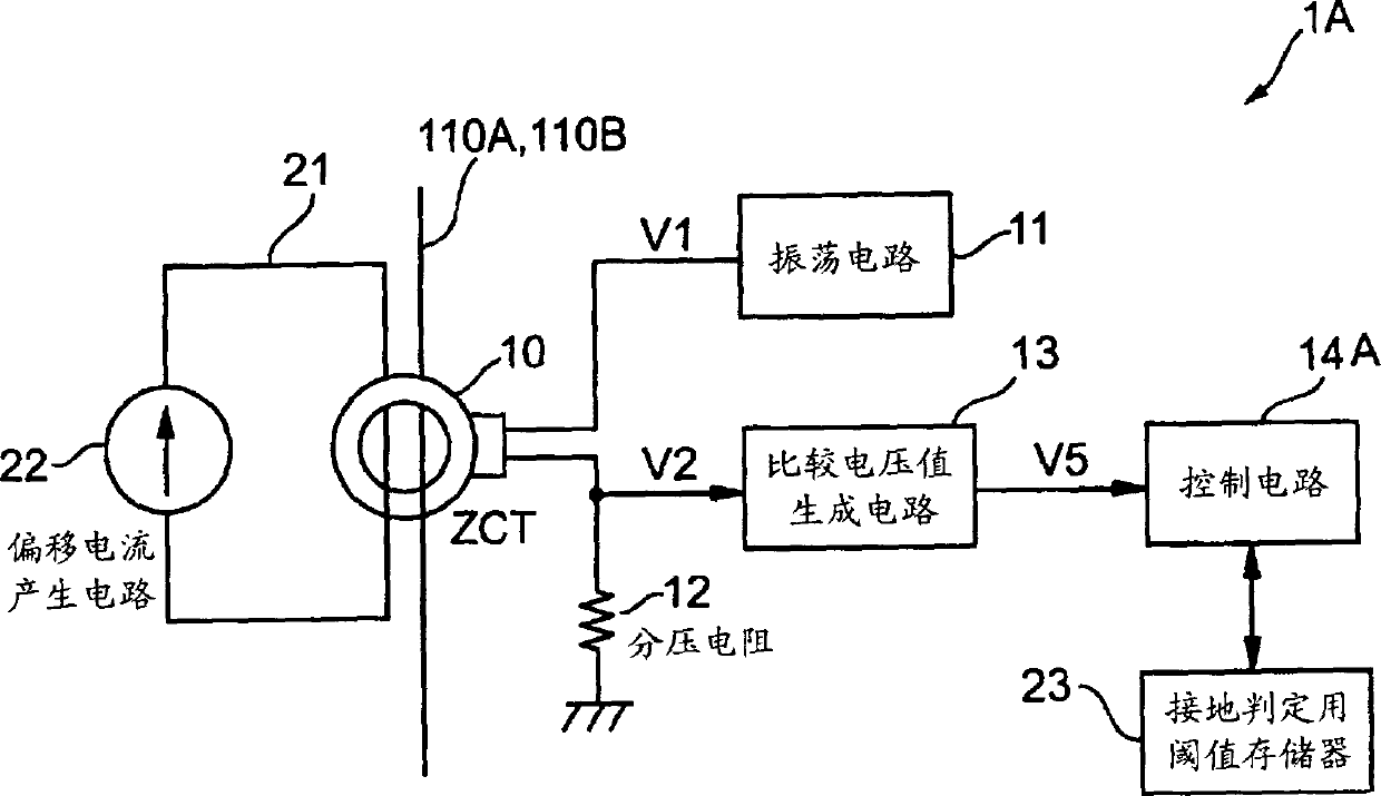
[0053] Next, a DC ground current detection circuit showing the first embodiment will be described. FIG. 1 is a block diagram showing a schematic configuration inside a DC ground current detection circuit of the first embodiment.
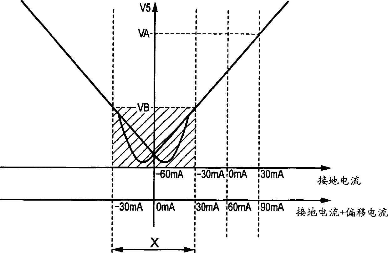
[0054] DC ground current detection circuit 1A shown in FIG. Pass ZCT10; Offset current generating circuit 22, as shown in Figure 2, will be subjected to the influence of the hysteresis characteristic of ZCT10 and it is difficult to detect the current range X of the DC current value of the DC ground current based on the comparison voltage value accurately (slope Line part) is converted into a detectable current range that can be detected based on a DC voltage value of a comparative voltage value of 5V, and an offset current is generated in the offset wire 21; the threshold value memory 23 for grounding determination stores and manages the current The DC ground current within the range of the DC current value corresponding to the grounding determinati...
Embodiment approach 2
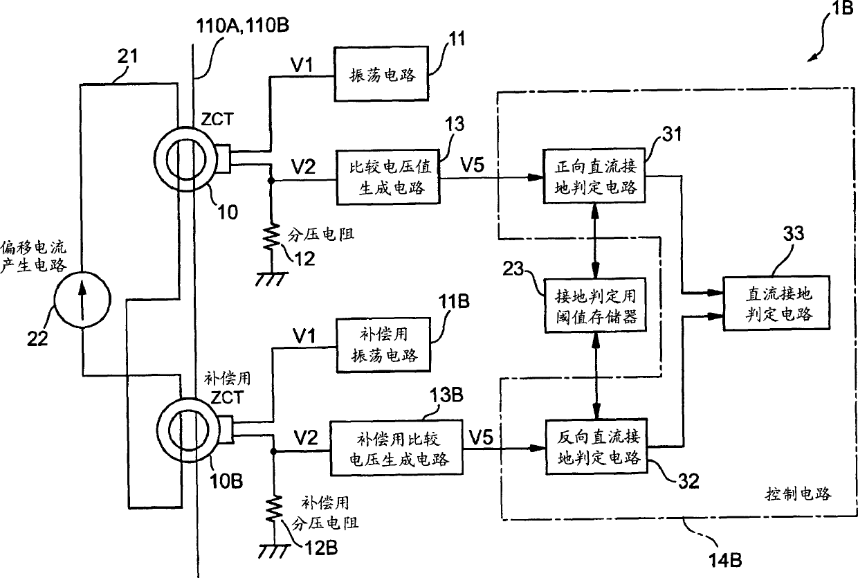
[0072] Here, a second embodiment will be described of a DC ground current detection circuit that can accurately detect whether the DC ground current is forward or reverse even when such a DC ground current suddenly occurs. 3 is a block diagram showing a schematic configuration inside a DC ground current detection circuit according to a second embodiment of the present invention. In addition, the same code|symbol is attached|subjected to the same part as DC ground current detection circuit 1A shown in FIG. 1, and the description of the overlapping structure and operation is abbreviate|omitted.
[0073]The DC ground current detection circuit 1B shown in FIG. 3 includes the ZCT 10 , the oscillator circuit 11 , the comparison voltage value generating circuit 13 , the offset current generating circuit 22 , and the grounding determination circuit 11 , which are electrically inserted through the source wires 110A, 110B and the offset wire 21. In addition to the memory 23, the power s...
Embodiment approach 3
[0101] Next, a DC ground fault detection circuit showing a third embodiment in which it is possible to accurately detect whether the DC ground current is forward or reverse even if a DC ground current suddenly occurs will be described. 6 is a block diagram showing a schematic configuration inside a DC ground current detection circuit according to a third embodiment of the present invention. In addition, since the same code|symbol is attached|subjected to the same part as DC ground current detection circuit 1A shown in FIG. 1, description of the overlapping structure and operation is abbreviate|omitted.
[0102] The DC ground current detection circuit 1C shown in FIG. 6 includes, in addition to the ZCT 10 inserted through the power supply lines 110A, 110B and the offset wire 21, the oscillation circuit 11, the comparison voltage value generation circuit 13, and the threshold value memory 23 for ground fault determination. : The offset current generation circuit 22C generates of...
PUM
 Abstract
Description
Claims
Application Information
 - R&D
- Intellectual Property
- Life Sciences
- Materials
- Tech Scout
- Unparalleled Data Quality
- Higher Quality Content
- 60% Fewer Hallucinations
Browse by: Latest US Patents, China's latest patents, Technical Efficacy Thesaurus, Application Domain, Technology Topic, Popular Technical Reports.
© 2025 PatSnap. All rights reserved.Legal|Privacy policy|Modern Slavery Act Transparency Statement|Sitemap|About US| Contact US: help@patsnap.com


