
Overturning stamp and overturning method

A seal and guide frame technology, applied in printing, stamping and other directions, can solve problems such as inconvenience in use, easy deformation of atomic stamp molds, etc., and achieve the effect of avoiding messy ink and novel structure design.

Inactive Publication Date: 2005-01-12
程志新
View PDF0 Cites 1 Cited by
  • Summary
  • Abstract
  • Description
  • Claims
  • Application Information

AI Technical Summary

Problems solved by technology

Its shortcomings: first, the atomic stamp mold is easily deformed; second, the oil content of the atomic stamp mold is disposable, and after use, it needs to be dipped in Indonesia like a rubber stamp, which is extremely inconvenient to use

Method used


Image

  • Overturning stamp and overturning method

Examples


Embodiment 1

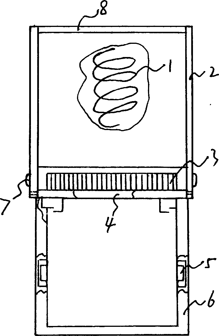
[0009] Embodiment 1: with reference to attached figure 1 . Flip the stamp, the guide frame 6 is molded by injection molding and is located in the stamp shell 2, and the upper end of the stamp shell 2 is provided with a transparent inlaid cover 8 for keeping and observing the stamp pattern. A compressed return spring 1 is interposed between the upper end of the guide frame and the seal case. Design spring self-locking structure 7 between seal shell and guide frame, spring self-locking structure 7 is prior art, do not narrate here. The drawer-type ink cartridge 3 adopts mold injection molding, the drawer-type ink cartridge 3 is located in the drawer guide hole on the upper part of the guide frame and can be pulled out and inserted, the turning shaft 4 is located at the lower part of the stamp shell and can be turned over, and the turning stamp body 4 is turned over The angle is 180 degrees. Turnover seal body 4 is made of turning body and seal, and seal adopts plastics or nyl...


PUM

PropertyMeasurementUnit
Flip angleaaaaaaaaaa

Abstract

A seal able to be turned or features that when it is not used, its front end is always in contact with the ink and when it is used for affixing, it can be turned over. It is composed of casing, seal, guider, restoring spring, and drawer-type ink box. Its turn-over method is also disclosed.

Description

Technical field: [0001] The invention relates to a reversible seal and a reversing method, belonging to the field of seal manufacturing. Background technique: [0002] The structure of the existing atomic seal is that the stamp mold is engraved with ink pad, the stamp mold is located in the stamp shell and is connected with the stamp handle, the stamp handle is equipped with a spring, when in use, press the stamp handle downward, and the stamp handle will press the stamp handle Push out from the stamp shell, and after the cover is completed, the stamp will automatically reset under the action of the return spring. Its shortcomings: first, the atomic stamp mold is easily deformed; second, the oil content of the atomic stamp mold is disposable, and after use, it needs to be dipped in Indonesia like a rubber stamp, which is extremely inconvenient to use. Invention content: [0003] The purpose of the design is to provide a portable reversing stamp and reversing method that c...

Claims


Application Information

Patent Timeline
IPC IPC(8): B41K1/02B41K1/36
Inventor 程志新
Owner 程志新
Learn More