
Distortion compensation circuit, distortion compensation signal generating method, and power amplifier

A technology of distortion compensation and power amplification, applied in amplifiers, improved amplifiers to reduce nonlinear distortion, parts of amplifiers, etc., can solve impractical problems

Inactive Publication Date: 2004-12-22
KOKUSA ELECTRIC CO LTD
View PDF1 Cites 7 Cited by
  • Summary
  • Abstract
  • Description
  • Claims
  • Application Information

AI Technical Summary

Problems solved by technology

[0005] As a method of updating the table, as described in the above-mentioned Non-Patent Document 1, the address of the table is equal to one scale, and in the method of obtaining the values ​​in all addresses by the perturbation method, it takes a considerable time to update, so , is extremely impractical

Method used


Image

  • Distortion compensation circuit, distortion compensation signal generating method, and power amplifier
  • Distortion compensation circuit, distortion compensation signal generating method, and power amplifier
  • Distortion compensation circuit, distortion compensation signal generating method, and power amplifier

Examples


Embodiment Construction

[0024] Hereinafter, embodiments of the present invention will be described.

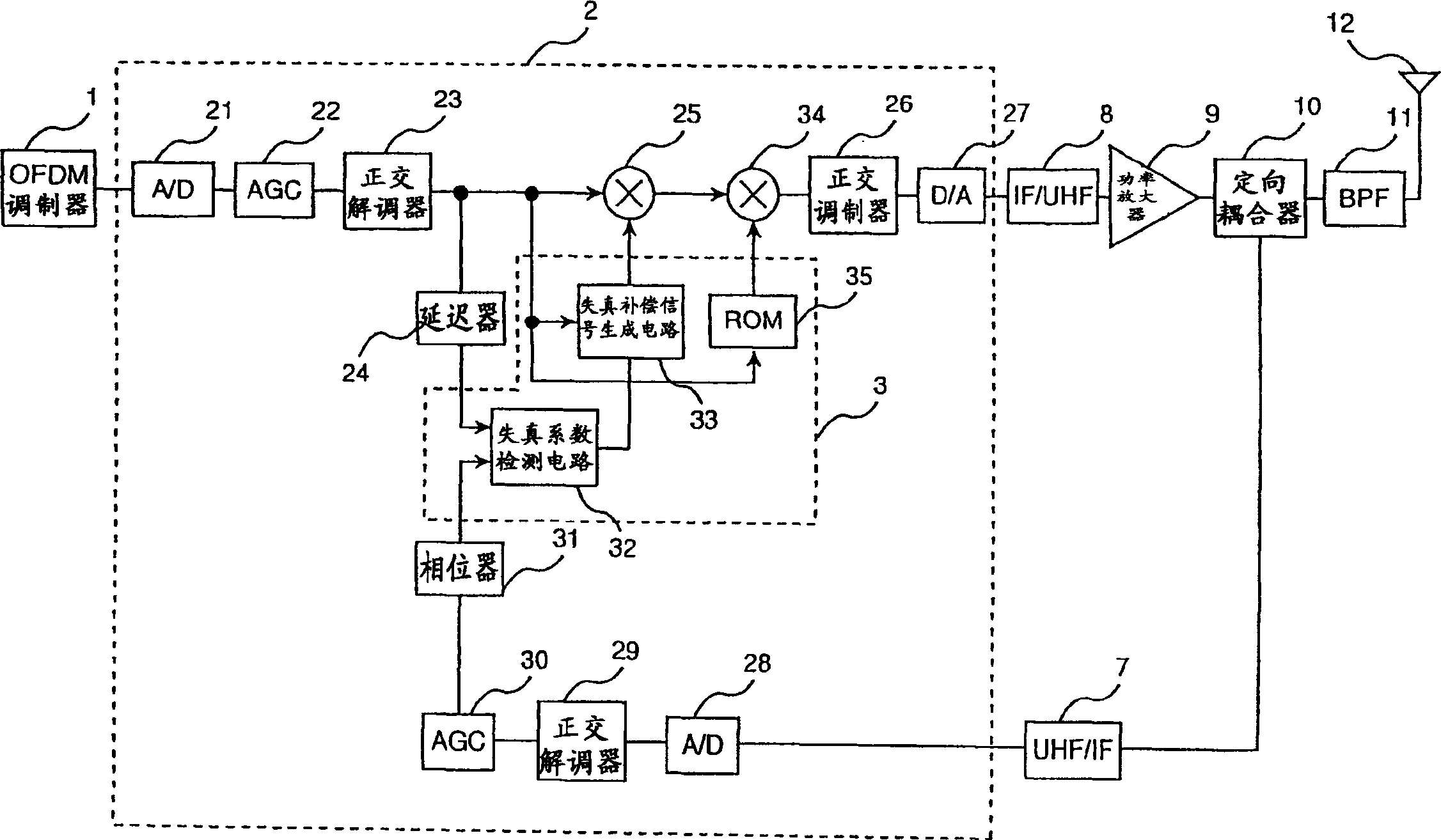
[0025] In the embodiment of the present invention, as the distortion compensation signal, two types of compensation signals corresponding to the input signal level are generated and used. One compensation signal is a compensation signal for automatic correction in which the amplitude level of the input signal corresponds to a relatively large level, and the other compensation signal is a compensation signal for fixed correction in which the amplitude level of the input signal corresponds to a smaller level. Signal.

[0026] First, the compensation signal for automatic correction will be described.

[0027] First, the principle for obtaining a distortion value generated by a power amplifier to generate a distortion compensation signal of an inverse characteristic will be described. Generally, the characteristics of the power amplifier circuit can be represented by the expanded formula shown in formula...


PUM


Abstract

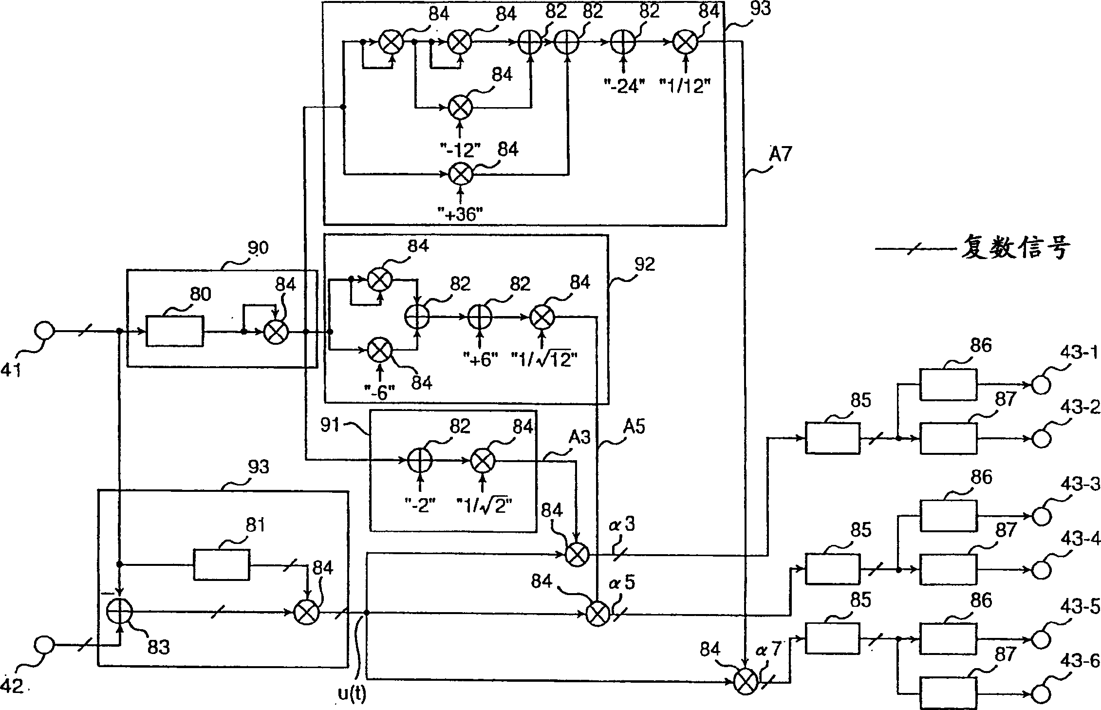
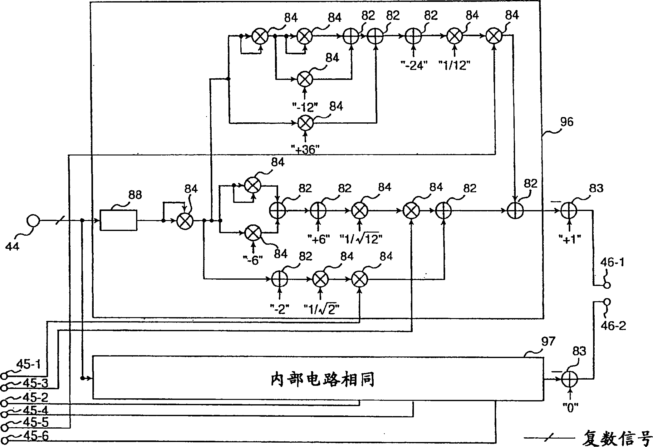
A distortion compensating circuit for a power amplifier attains raised compensating accuracy with shorter convergence time by accurately and quickly generating a distortion compensation signal for pre-distortion. An error signal representing the difference between the input and output signals of the power amplifier is generated. From the error signal and the input signal, the coefficients of the third-order intermodulation distortion, fifth-order intermodulation distortion and seventh-order intermodulation distortion are calculated. According to these coefficients, a distortion compensating signal which is characteristically opposite in phase and gain to the intermodulation distortions is generated.

Description

technical field [0001] The present invention relates to a nonlinear distortion compensation technique for reducing a nonlinear distortion component output from a transmitting device that transmits radio waves amplified by a power amplifier. Background technique [0002] As an example of the existing nonlinear distortion compensation technology, especially the technology of pre-distortion compensation method, for example, there are disclosed in Ying Qing Xue Ji Bao Vol.24, No.79, BCS2000-92, "Adaptive pre-distortion compensation The technology described in "Distortion Compensated Power Amplifier" (Non-Patent Document 1). here, Figure 5 shows an example of a block configuration of a transmitting device including a conventional power amplifier. Hereinafter, the Figure 5 Describe the technique. [0003] exist Figure 5 Among them, the signal to be transmitted, that is, the input signal, passes through the distributor 51, the delay element 52, the phase adjuster 53, the gain a...

Claims


Application Information

Patent Timeline
Patent Type & Authority Applications(China)
IPC IPC(8): H03F1/32
CPCH03F1/3247H03F1/3282
Inventor 广濑伸郎塚本信夫郁丸史人佐野诚一
Owner KOKUSA ELECTRIC CO LTD
Learn More