Optoelectronic device for detecting position and movement and method associated therewith

A technology for optoelectronic devices and measuring devices, applied in the direction of using optical devices, measuring devices, electronic switches, etc., can solve problems such as distraction

Inactive Publication Date: 2004-10-27
格尔德·赖梅
View PDF1 Cites 17 Cited by
  • Summary
  • Abstract
  • Description
  • Claims
  • Application Information

AI Technical Summary

Problems solved by technology

However, since the user actually has to enter the travel path according to the prerequisites of the corresponding system, with this type of operation, it is easy to cause distraction

Method used


Image

  • Optoelectronic device for detecting position and movement and method associated therewith
  • Optoelectronic device for detecting position and movement and method associated therewith
  • Optoelectronic device for detecting position and movement and method associated therewith

Examples


Embodiment Construction

[0026] Detailed Description of Preferred Embodiments

[0027] The present invention is explained in detail by way of examples with reference to the accompanying drawings, but the examples are by way of example only and are not intended to limit the invention to a specific arrangement.

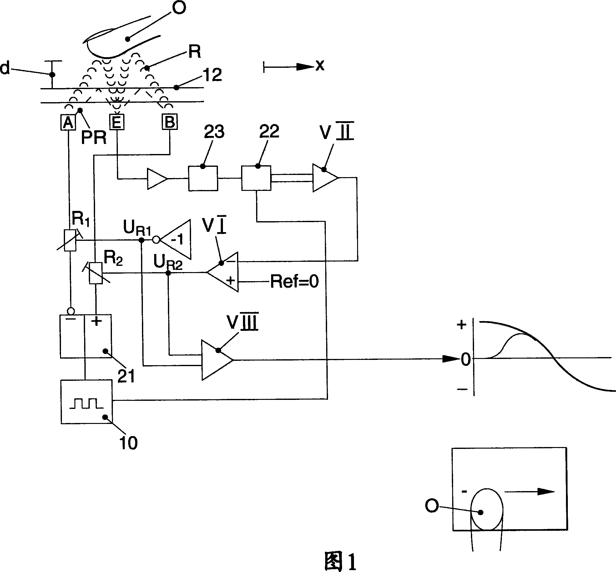
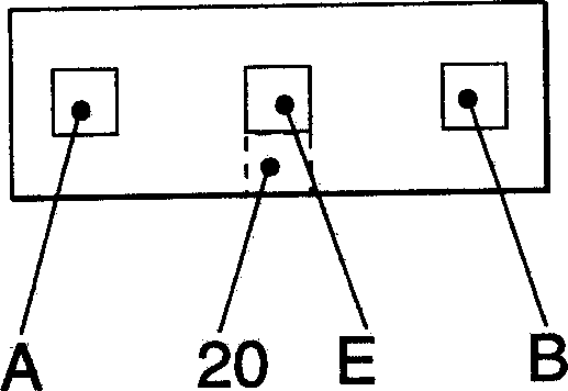
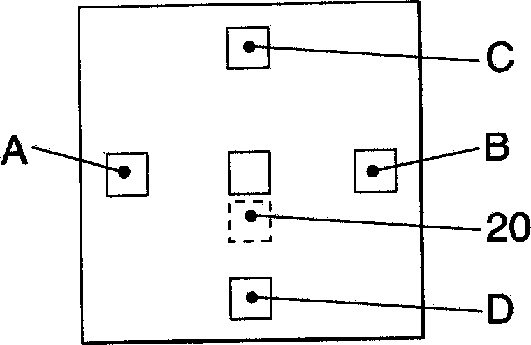
[0028] The figure shows an optoelectronic device for detecting the position and / or movement of an object O, which has a plurality of emitters A, B, C, D for emitting light rays. At least one receiver E or E1-E4 is associated with the emitters to receive the rays emitted by the emitters A-D and reflected back from the object O. If the target O has an emitter, no reflections are needed and the ray will be emitted directly by the target. Depending on the connections, several mutually distinct radiation paths (ray paths in the case of light), involving at least some of the emitters A-D and at least one receiver E, E1-E4, are arranged between the emitter, the target, and the receiver between. The...


PUM


Abstract

Optoelectronic device and method for detecting the position and / or movement of an object, the device and method include: a plurality of transmitters for emitting radiation, at least one receiver for receiving the radiation emitted by the transmitters and reflected back by the object or the radiation emitted from transmitters associated with the object, a plurality of mutually different radiation paths, which are formed between at least a part of the transmitters, the object and the receivers or between transmitters associated with the object and the receivers, a timing circuit for cycled switching of the transmitters of the different radiation paths, an evaluation device, which converts the signals received by the receivers for the different radiation paths into values for detection of the position and / or movement of the object along a line or in a surface, wherein for three-dimensional detection of the position and / or movement of the object, the timing circuit switches a plurality of, but at least a part of the transmitters and / or receivers in at least one further cycle such that the space, into which the transmitters emit, is illuminated nearly uniformly, and that the evaluation device determines a value for determination of the distance of the object from the line or surface on the basis of the radiation radiated or radiated back by the object during the further cycle.

Description

[0001] Related application reference [0002] This application claims priority from German Patent Application No. 10133823.6 filed on July 16, 2001, the entire content of which is hereby incorporated by reference. field of invention [0003] The invention relates to an optoelectronic device and a method for detecting the position and / or movement of an object according to the preamble of claim 1 or 34 . Background technique [0004] In European patent application EP706648A1 an optical system for detecting changes in reflected light from an object is disclosed, wherein changes in extraneous light have no influence on the measured value. This system is mainly used as a wiper sensor to detect raindrops hitting the windshield. It can also be used as a proximity sensor (proximity sensor). If the photoelectric measurement path is a planar structure at this time, two-dimensional value to determine the location and / or movement of the measurement target. [0005] Such devices also t...

Claims


Application Information

Patent Timeline
Patent Type & Authority Applications(China)
IPC IPC(8): G01B11/00G01B11/03G06F3/0346G06F3/042H03K17/96
CPCG06F3/0346G06F3/0421
Inventor 格尔德·赖梅
Owner 格尔德·赖梅
Why Eureka
Try Eureka