
Reciprocating electric razor

An electric razor and type technology, applied in the field of reciprocating type electric razors, can solve problems such as insufficient shaving

Inactive Publication Date: 2004-09-08
IZUMI PROD CO
View PDF0 Cites 3 Cited by
  • Summary
  • Abstract
  • Description
  • Claims
  • Application Information

AI Technical Summary

Problems solved by technology

During this shave, shaving stubble is formed, and the shave is not sufficient

Method used


Image

  • Reciprocating electric razor
  • Reciprocating electric razor
  • Reciprocating electric razor

Examples


Embodiment Construction

[0029] Preferred embodiments of the present invention are described in detail below.

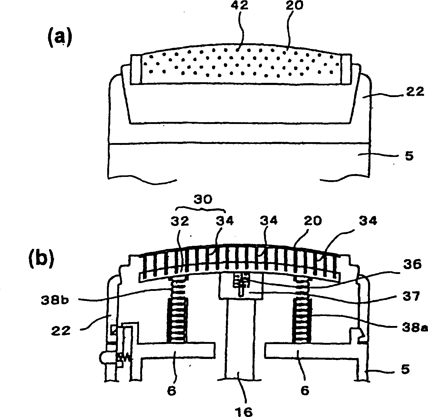
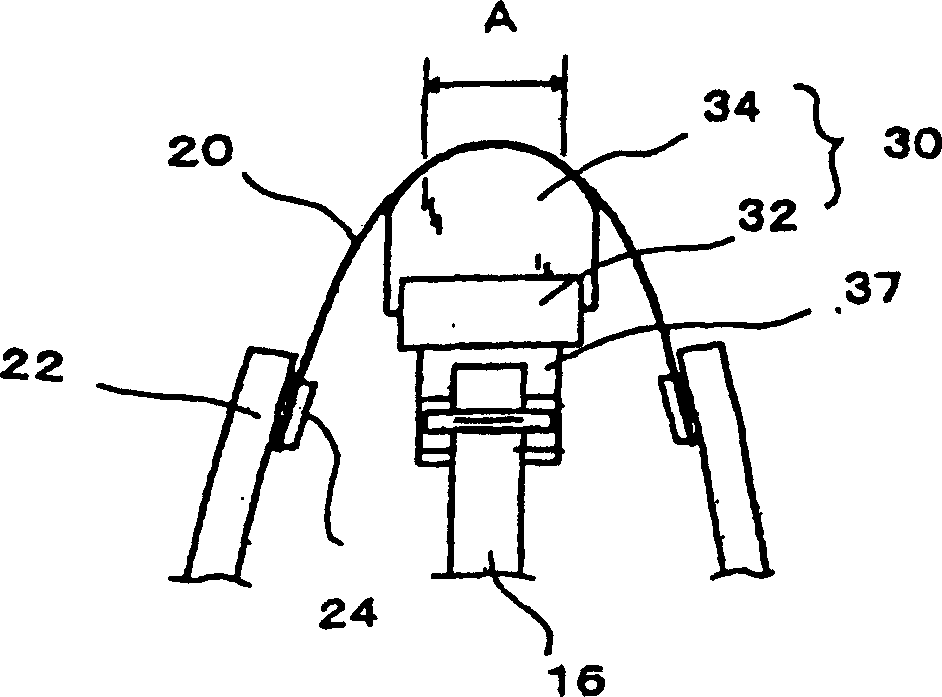
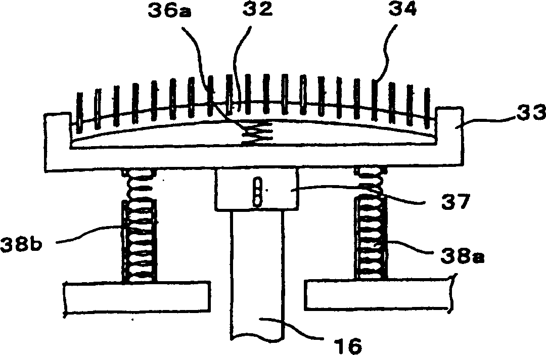
[0030] figure 1 (a) and 1(b) show an embodiment of the reciprocating type electric razor of the present invention, showing the inner and outer cutting blades of the reciprocating type electric razor of the present invention. figure 1 (a) shows an external view of the outer cutting tool 20, and 1(b) shows the outer cutting tool 20 and the inner cutting tool 30 in the electric shaver.

[0031] exist figure 1 (a) and 1(b), no external force acts on the outer cutting tool 20, such as figure 1 As shown in (a), in the illustrated embodiment of the present invention, when no external force acts on the outer cutting tool 20, the top of the outer cutting tool 20 is configured to be bent outward or in a convex shape.

[0032] In the reciprocating type electric shaver of the illustrated embodiment, the outer cutting blade 20 has elasticity (flexibility) so that the shape of the outer surface (to...


PUM


Abstract

A reciprocating type electric shaver including an outer cutter, an inner cutter in which a plurality of cutter blades that make sliding contact with the inside surface of the outer cutter are disposed on a cutter blade supporting body in a straight row in the direction of length of the outer cutter, and a driving mechanism that causes the inner cutter to make a reciprocating motion in the direction of length of the outer cutter; wherein the outer cutter is formed so as to deform into a curved shape such as a convex shape that protrudes outward or a concave shape that protrudes inward, and the cutter blade supporting body is formed so as to bend into a curved shape in conformity with the outer cutter.

Description

technical field [0001] The present invention relates to a reciprocating type electric shaver, and more particularly to a reciprocating type electric shaver in which the outer surface of the outer cutting blade can be deformed into a curved shape corresponding to the pressure applied during shaving. Background technique [0002] Figure 9 (a) shows the outer cutting tool portion of a general reciprocating type electric razor, Figure 9 (b) shows the structure of the inner and outer cutting tools of this common reciprocating type electric razor. [0003] The outer cutting tool 10 is made of a thin metal plate on which a hair introduction hole is formed, the thin metal plate is bent into an inverted U shape (when viewed from the side) and installed so that the outer surface extends from the upper part of the main body 5 of the electric shaver. be exposed. [0004] At the same time, if Figure 9 The inner cutting tool 12 is set as shown in (b), so that the inner cutting tool is...

Claims


Application Information

Patent Timeline
IPC IPC(8): B26B19/04
CPCB26B19/046
Inventor 内山圣参
Owner IZUMI PROD CO
Learn More