Scan conversion appts.
A technology of conversion device and conversion circuit, which is applied in the direction of standard conversion, movie film standard conversion, television, etc., and can solve problems such as image degradation
- Summary
- Abstract
- Description
- Claims
- Application Information
AI Technical Summary
Problems solved by technology
Method used
Image

Examples
Embodiment 1
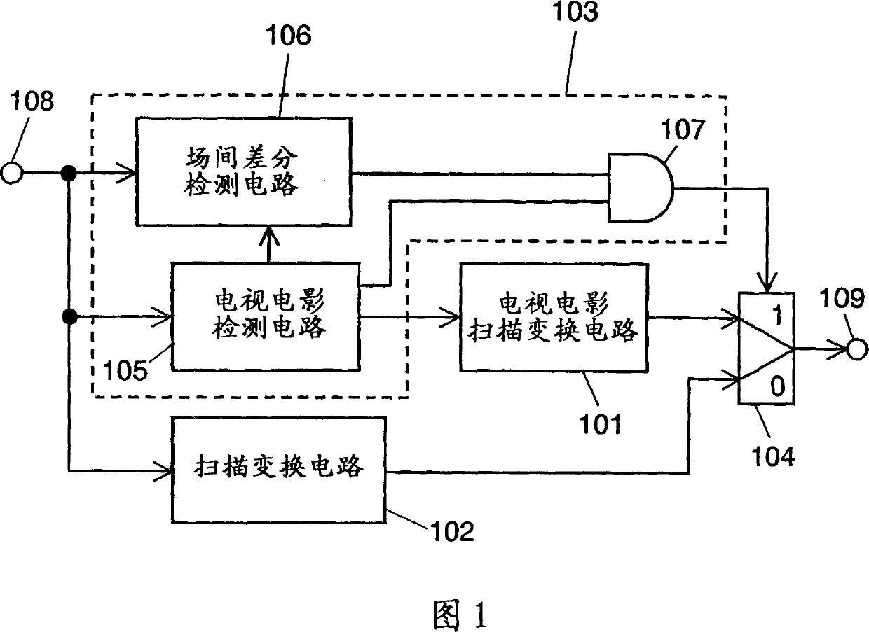
[0036] Fig. 1 is a block diagram of a scan conversion device according to Embodiment 1 of the present invention. In FIG. 1 , a video signal is input through a video signal input terminal 108 . The input video signal is an interlaced video signal, and is supplied to a scan conversion circuit 102 , a telecine detection circuit 105 , and an interfield difference detection circuit 106 . The telecine detection circuit 105 , the field difference detection circuit 106 and the first AND circuit 107 constitute the video signal judgment circuit 103 .
[0037]The scan conversion circuit 102 compares the input video signal with the fields or frames before and after it, and detects whether it is a moving image area, a still image area, or an intermediate area between a moving image and a still image. In the still image area, The scan line interpolation is performed using the information of the front and back fields, and the scan line interpolation is performed using the information of the...
Embodiment 2
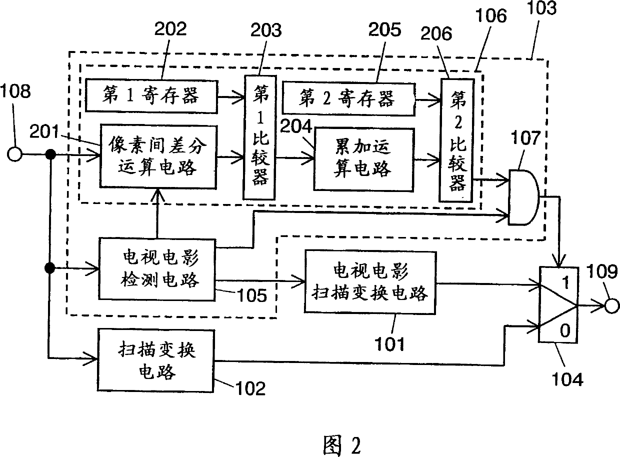
[0045] FIG. 2 is a block diagram showing a detailed configuration of inter-field difference detection circuit 106 of FIG. 1 according to Embodiment 1 of the present invention.
[0046] Matters that are described in Embodiment 1 but not described in Embodiment 2 are still applicable in Embodiment 2, and detailed descriptions are omitted.
[0047] In FIG. 2 , the inter-field difference detection circuit 106 is composed of an inter-pixel difference operation circuit 201 , a first register 202 , a first comparator 203 , an accumulation operation circuit 204 , a second register 205 , and a second comparator 206 .
[0048] The inter-pixel difference calculation circuit 201 takes the difference in luminance signal levels between pixels located at the same position in two fields of one frame that may be generated from the same screen of a movie. The so-called between pixels located at the same position refers to pixels with the same number of horizontal scanning lines counted accordin...
Embodiment 3
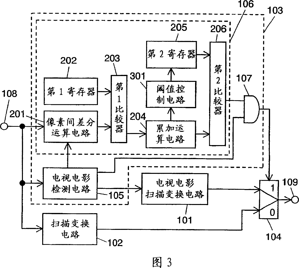
[0060] Fig. 3 is a block diagram showing an image conversion device according to the third embodiment. This figure is the same as that of FIG. 2 except for the threshold control circuit 301 .
[0061] The second threshold stored in the second register 205 in FIG. 2 is a fixed value. However, in FIG. 3 , the second threshold stored in the second register 205 is controlled by the threshold control circuit 301 .
[0062] Take, for example, a video signal having a flat image with many regions like a cartoon. In a video signal with many areas including flat images, there are many areas where the pixel difference value calculated by the inter-pixel difference calculation circuit 201 is small. As a result, even if the sum of the differences of one field is calculated in the accumulating circuit 204, the sum is very small, and there may be a case where an edit point or the like of the telecine video signal cannot be detected.
[0063]In order to prevent such a malfunction, the thre...
PUM
 Abstract
Description
Claims
Application Information
 - Generate Ideas
- Intellectual Property
- Life Sciences
- Materials
- Tech Scout
- Unparalleled Data Quality
- Higher Quality Content
- 60% Fewer Hallucinations
Browse by: Latest US Patents, China's latest patents, Technical Efficacy Thesaurus, Application Domain, Technology Topic, Popular Technical Reports.
© 2025 PatSnap. All rights reserved.Legal|Privacy policy|Modern Slavery Act Transparency Statement|Sitemap|About US| Contact US: help@patsnap.com