
Orthodontic distallizing appliance

A technology of equipment and orthodontics, applied in the field of equipment, can solve problems such as complex structural arrangements

Inactive Publication Date: 2004-02-18
凯文C 沃尔德
View PDF4 Cites 13 Cited by
  • Summary
  • Abstract
  • Description
  • Claims
  • Application Information

AI Technical Summary

Problems solved by technology

The instrument of the US5,785,520 patent is more complicated than Hilger's instrument in terms of the structural arrangement of each part, and needs to be adjusted on both sides of the instrument
[0005] None of the known prior art instruments incorporate a centrally located threaded adjustment member in order to apply different forces to the molars on which the rearward force is applied

Method used


Image

  • Orthodontic distallizing appliance
  • Orthodontic distallizing appliance
  • Orthodontic distallizing appliance

Examples


Embodiment Construction

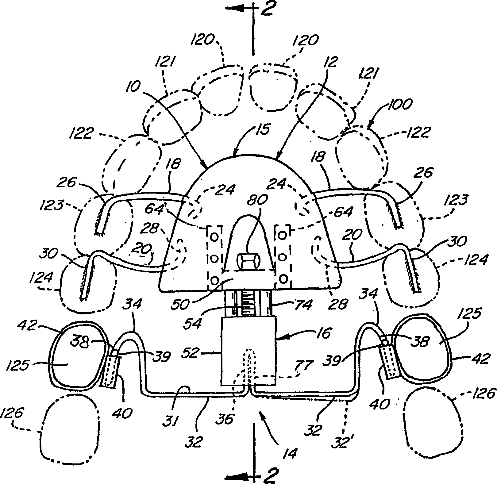
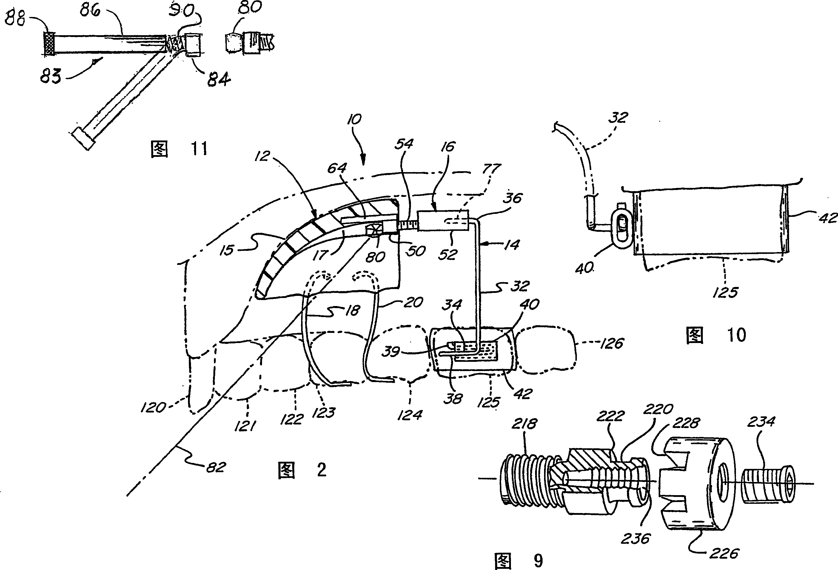
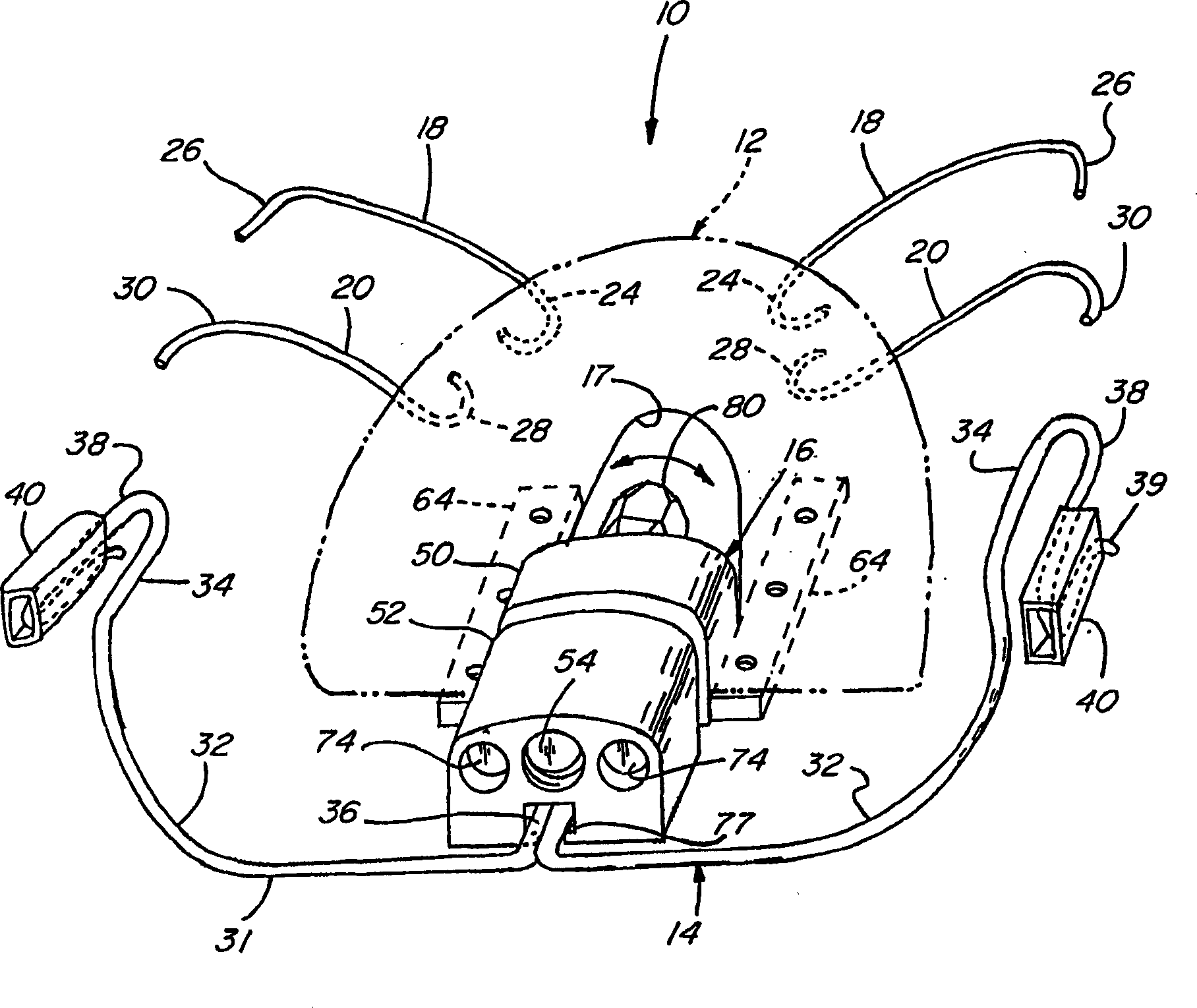
[0039] Now, referring to the drawings by reference numerals, first look at Figure 1-3 , it can be understood that the instrument 10 intends to achieve the purpose of moving the molars back by applying a controlled pressure, which comes from a fixed Nance tray or other fixed devices, such as an intraosseous implant device.

[0040] The instrument 10 is used in the part of the oral cavity commonly referred to as the upper dental arch, specifically the jaw, indicated by the numeral 100, and has a number of teeth arranged in an arcuate configuration near the roof of the mouth, particularly the jaw region 102. . The dental arch is further formed by the bottom gums which provide the foundations for the oppositely disposed teeth, including incisors 120 and 121 , canines 122 , premolars or premolars 123 and 124 , and molars 125 and 126 .

[0041] The instrument 10 basically comprises a frontally configured support and fixation assembly 12, a spring assembly 14 and an adjustment devi...


PUM


Abstract

This orthodontic distalizing appliance (10) includes a forward support assembly (12) having an anchoring base (15) in the roof of the mouth. A rearward laterally disposed spring assembly (14) is provided having outer ends (34, 38) removably received within associated sheaths (40) attached to maxillary molars (25). A centrally disposed adjustment assembly (16) extends between the anchoring base (15) and the spring assembly (14) for applying a force to the spring assembly (14) which is transmitted to the molars (125) to be distalized.

Description

technical field [0001] In general, the present invention relates to instruments for correcting malocclusion problems without molar setback, and more particularly to an instrument utilizing a front fixation assembly, a rear spring assembly, and a A threaded adjustment device for rearward movement. Background technique [0002] One of the most well-known instruments used in modern orthodontics to correct Class II malocclusions is the Pendulum instrument in an article by James J. Hilgers, Journal of Clinical Orthontics, November 1992, pp. 706-714 Described in the article entitled The Pendulum Appliance for Class II Non-Compliance Therapy, which is hereby incorporated by reference. The Pendulum appliance uses a large Nance acrylic tray in the upper palate with a spring assembly secured to the upper premolars by a wire attachment, the spring assembly is secured in the center of the tray and the first between the upper molars so that a slight continuous force can be applied to t...

Claims


Application Information

Patent Timeline
Patent Type & Authority Applications(China)
IPC IPC(8): A61C7/08A61C7/00A61C7/10A61C8/00
CPCA61C8/0096A61C7/10A61C7/00
Inventor 凯文C·沃尔德
Owner 凯文C 沃尔德
Learn More