
Magnetron

A magnetron and metal tube technology, applied in the field of magnetrons, can solve the problems of insufficient 3rd harmonic noise level and failure to play the role of high harmonic suppression choke.

Inactive Publication Date: 2004-02-04
PANASONIC CORP
View PDF0 Cites 7 Cited by
  • Summary
  • Abstract
  • Description
  • Claims
  • Application Information

AI Technical Summary

Problems solved by technology

However, even when these magnetrons are used in microwave ovens, from Figure 11 As can be seen from the noise level curve shown in Figure 14, compared with other high-order harmonics, the suppression of the noise level of the 3rd harmonic is not sufficient, especially in the low sideband of 6.9±0.15GHz around the 3rd harmonic In the high sideband of 8.3±0.15GHz, there is a problem that the role of the high-order harmonic suppression choke is not exerted

Method used


Image

  • Magnetron
  • Magnetron
  • Magnetron

Examples


Embodiment Construction

[0055] Next, a magnetron according to a preferred embodiment of the present invention will be described in detail with reference to the accompanying drawings.

[0056] 1st embodiment

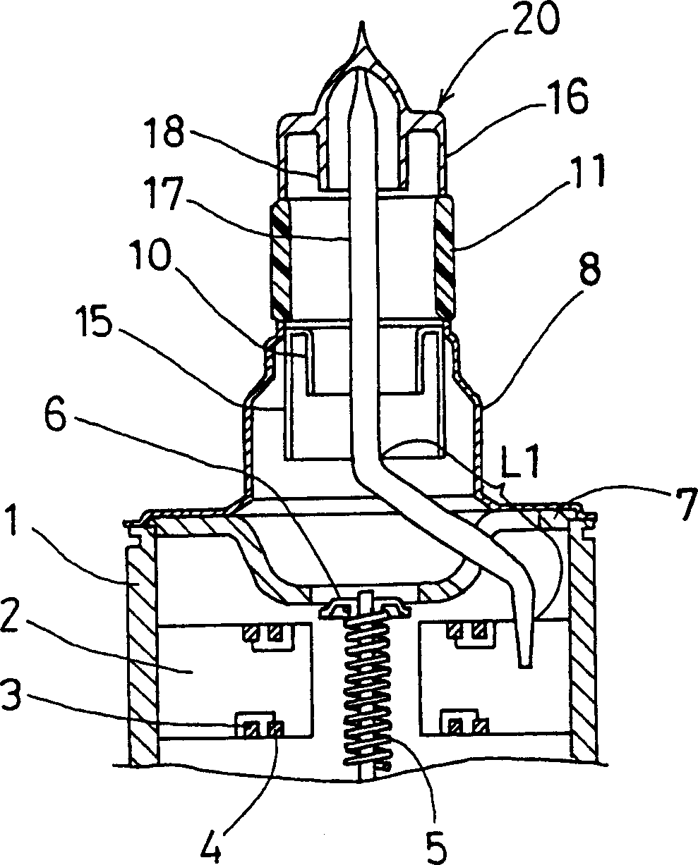
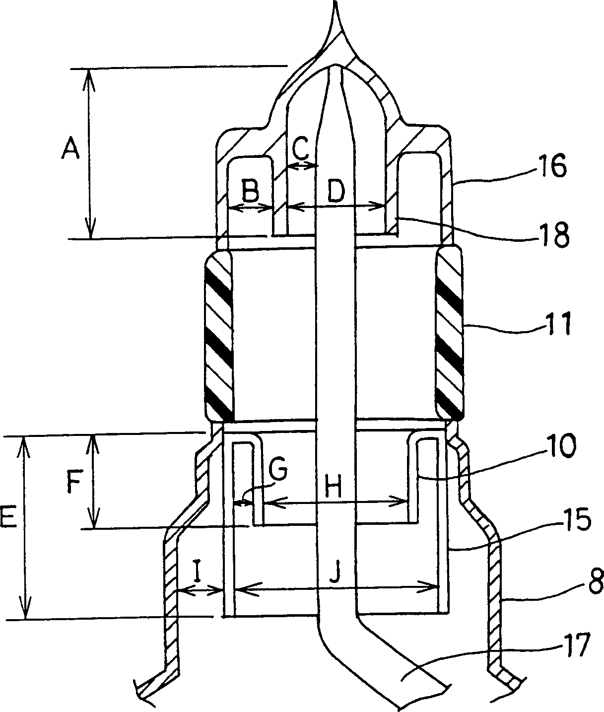
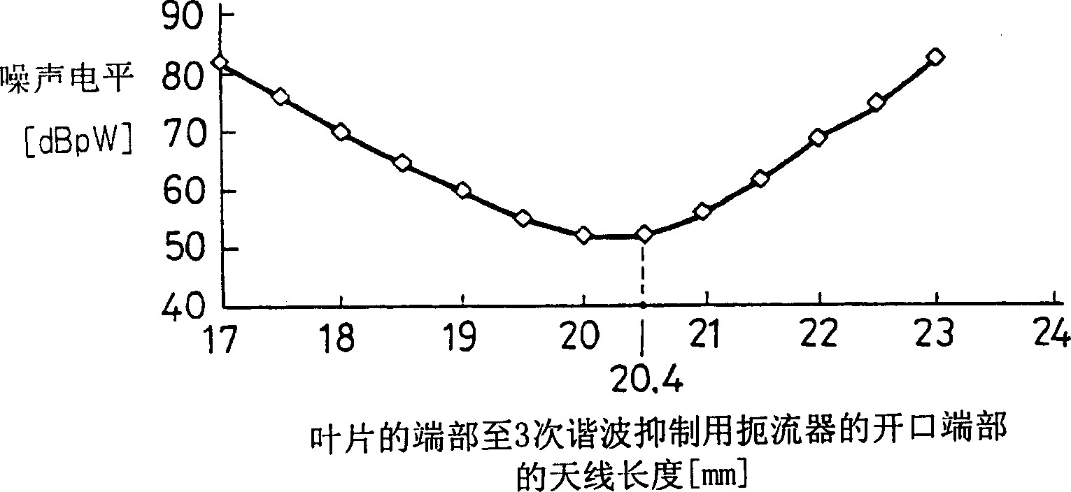
[0057] figure 1 It is a sectional view showing the main part of the first embodiment of the magnetron according to the present invention. figure 2 It is an enlarged cross-sectional view showing dimensions of main parts in the magnetron of the first embodiment. image 3 It is a graph showing the relationship between the length from the blade end of the antenna reed to the choke for third harmonic suppression and the noise level in the magnetron according to the first embodiment. Figure 4 It is a graph showing in detail the noise level in the frequency range around the third harmonic in the microwave oven using the magnetron of the first embodiment.

[0058] Such as figure 1 As shown, in the magnetron of the first embodiment, a plurality of plate-shaped vanes 2 are fixed on the inner wall ...


PUM


Abstract

A magnetron in accordance with the present invention is configured so that an antenna lead (17) connected to a desired position of an anode segment (2) passes through a magnetic pole piece (7) and a metal cylinder (8) so as not to make contact therewith and is connected to the output portion (20) of the magnetron, and so that the electrical length L1 of this antenna lead (17) between the opening end of a third harmonic restraint choke (15) and the connection portion of the anode segment (2) is 1 / 2 of the wavelength (lambda) of the third harmonic, thereby restraining the third harmonic and the side bands of the third harmonic.

Description

Background of the invention [0001] The present invention relates to magnetrons used in microwave ovens and the like, and more particularly to a mechanism for suppressing leakage of high-order resonance wave components from output portions of the magnetrons. [0002] In a magnetic tube used in a microwave oven, a microwave of 2.45 GHz is generally generated as a fundamental wave. When the magnetron generates microwaves, in addition to the fundamental wave, it also simultaneously generates high-order harmonic components with frequencies that are integer multiples of the fundamental wave. When this harmonic component is radiated from the output portion, the harmonic propagates into the microwave oven similarly to the fundamental wave. Since the wavelength of the harmonic is short, once the wave propagates in the microwave oven, it is difficult to prevent leakage to the outside of the microwave oven. Leakage electric power leaking to the outside of the microwave oven may cause a...

Claims


Application Information

Patent Timeline
Patent Type & Authority Applications(China)
IPC IPC(8): H01J23/54H01J23/15H01J23/40H01J23/44H01J25/50H01J25/587
CPCH01J23/54H01J25/587H01J23/15
Inventor 石井健齋藤悦扶吉原正訓塚田敏行大栗英樹
Owner PANASONIC CORP
Learn More