
Circuit for frequency synthesizer

A frequency synthesizer and circuit technology, applied in the direction of electrical components, automatic power control, etc., can solve problems such as noise component leakage

Inactive Publication Date: 2003-12-10
SPANSION LLC
View PDF0 Cites 0 Cited by
  • Summary
  • Abstract
  • Description
  • Claims
  • Application Information

AI Technical Summary

Problems solved by technology

[0006] It is possible to design the input of the VCO so that the terminals are exposed to the outside, but due to the leakage of a small amount of noise components from the input terminals exposed to the outside during the switch-off mode (i.e., non-test mode), it will affect the noise of the frequency synthesizer circuit. feature has adverse effects, so this cannot be used

Method used


Image

  • Circuit for frequency synthesizer
  • Circuit for frequency synthesizer
  • Circuit for frequency synthesizer

Examples


Embodiment Construction

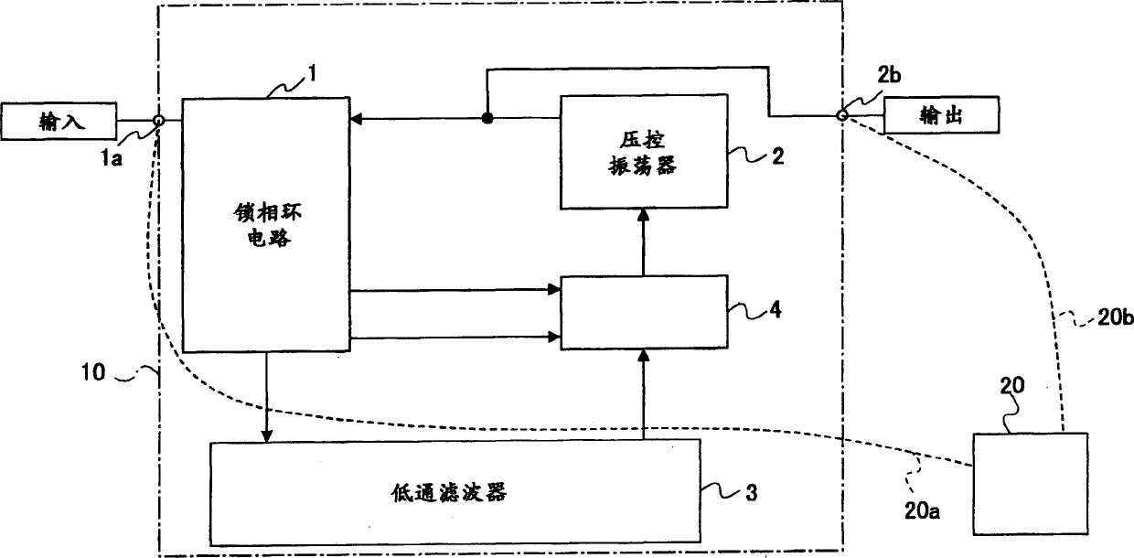
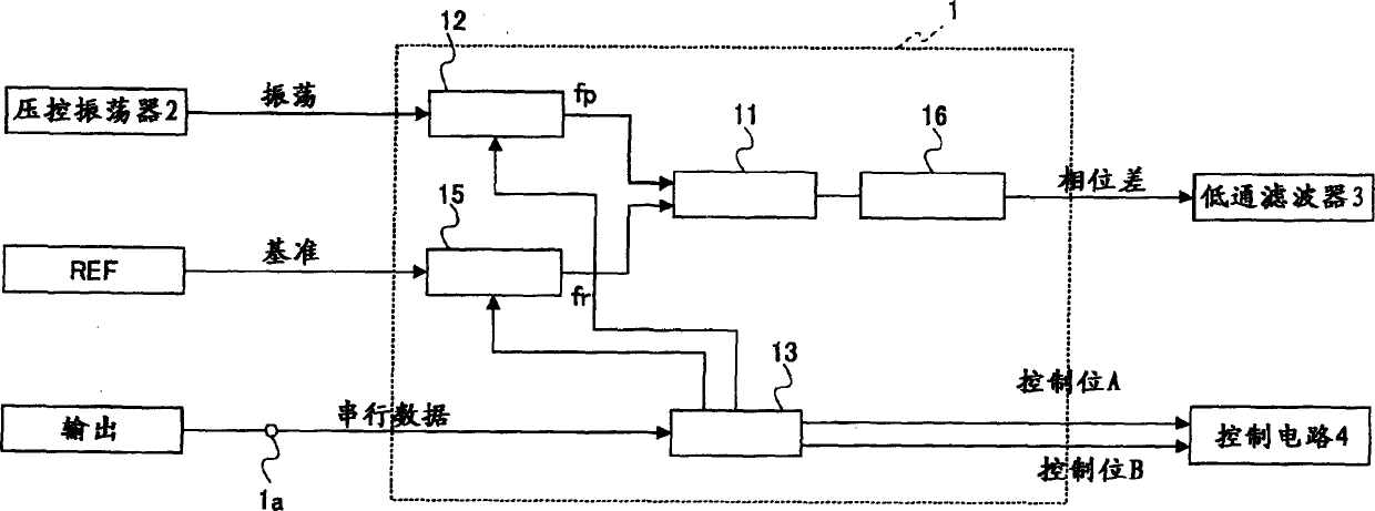
[0031] 2-6, the following is a description of the frequency synthesizer circuit according to the first embodiment of the present invention. 2 is a general schematic block diagram of the frequency synthesizer circuit according to the first embodiment, FIG. 3 is a detailed block diagram of the PLL circuit in the frequency synthesizer circuit according to the first embodiment, and FIG. Figure 5 is a detailed block diagram of the control circuit in the frequency synthesizer circuit according to the first embodiment, and Figure 6 is a diagram showing the characteristics of the voltage-controlled oscillator in the frequency synthesizer circuit according to the first embodiment Logic diagram (truth table) of the control circuit in the frequency synthesizer circuit of the embodiment.

[0032] In each of the above-mentioned figures, the frequency synthesizer circuit 10 according to the first embodiment of the present invention includes: a PLL circuit 1, a voltage-controlled oscillator ...


PUM


Abstract

The frequency synthesizer circuit includes a phase-locked loop (PLL) circuit, a voltage controlled oscillator (VCO), a low pass filter (LPF), an input terminal for providing serial data provided from the exterior to the PLL circuit, an output terminal for providing an oscillation signal provided the VCO, and a testing unit providing a testing voltage with a binary value to the VCO, wherein, the PLL circuit, the VCO, the LPF, and the testing unit are mounted on a single chip, and usability of the frequency synthesizer circuit is determined based on the oscillation signal provided from the VCO via said output terminal according to the testing voltage with a binary value provided from said testing unit.

Description

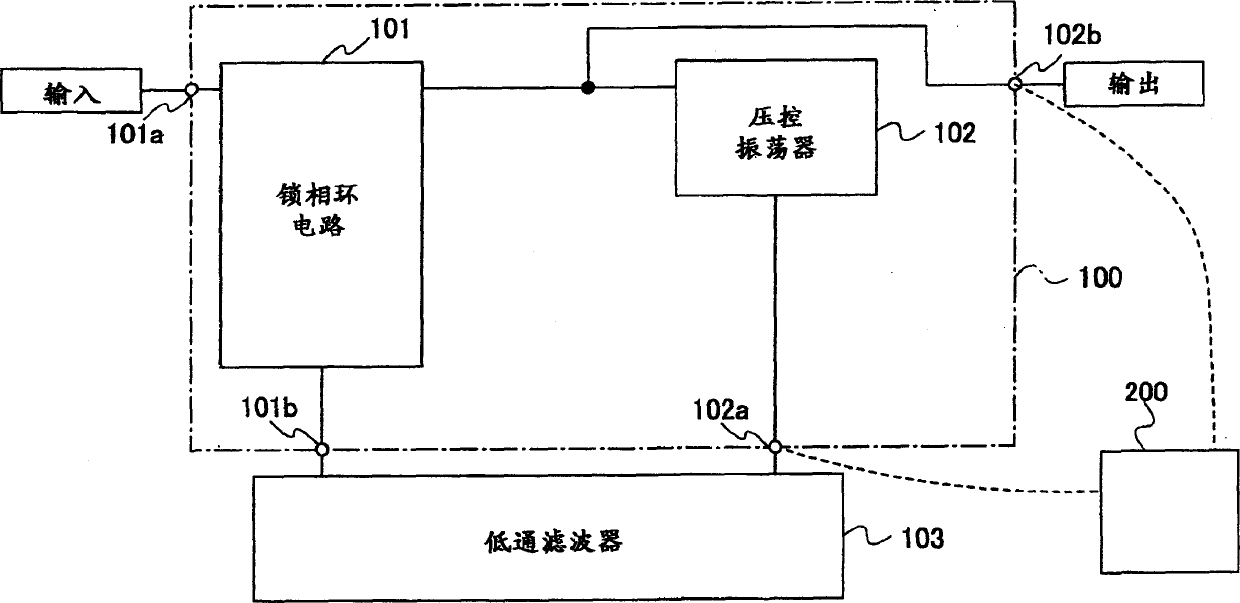
technical field [0001] The present invention relates to frequency synthesizer circuits using phase locked loop (PLL) circuits. Background technique [0002] As shown in FIG. 1 , a frequency synthesizer circuit according to the related art used in a cellular phone or the like (in which the frequency synthesizer generates an output signal in phase with an input signal) includes a PLL circuit 101 which is a digital circuit, a voltage-controlled circuit 101 which is an analog circuit An oscillator (VCO) 102 and a low pass filter (LPF) 103 . The PLL circuit 101 and the VCO 102 are mounted on a single substrate 100 . Terminals 101a, 101b, 102a, and 102b are formed on the substrate 100 and the terminals 101b, 102a are connected to the outside of the LPF 103 . [0003] In such a configuration, when the VCO 102 is to be subjected to a so-called wafer probing test operation, a control voltage is supplied from a probe of the test apparatus 200 connected to the (input) terminal 102a, ...

Claims


Application Information

Patent Timeline
Patent Type & Authority Applications(China)
IPC IPC(8): H03L7/08H03L7/18
CPCH03L7/18H03L7/16
Inventor 本吉俊朗永田公彦
Owner SPANSION LLC
Learn More