
Robot arm mechanism and robot device

A technology of robotic arms and connectors, used in transportation and packaging, claw arms, manipulators, etc.

Inactive Publication Date: 2003-11-12
TEIJIN SEIKI CO LTD
View PDF1 Cites 8 Cited by
  • Summary
  • Abstract
  • Description
  • Claims
  • Application Information

AI Technical Summary

Problems solved by technology

This causes the range of pivot movement to be limited to accommodate the second link 962, the third link 963, and the outside dimensions of the first arm links 931 and 932 of the first and second robot arms 910a and 910b, the second link 962 The distance between the centerline of the first robot arm 910a and the centerline of the first arm link 931, and the centerline of the third link 963 and the centerline of the first arm link 932 of the second robot arm 910b distance between

Method used


Image

  • Robot arm mechanism and robot device
  • Robot arm mechanism and robot device
  • Robot arm mechanism and robot device

Examples


Embodiment Construction

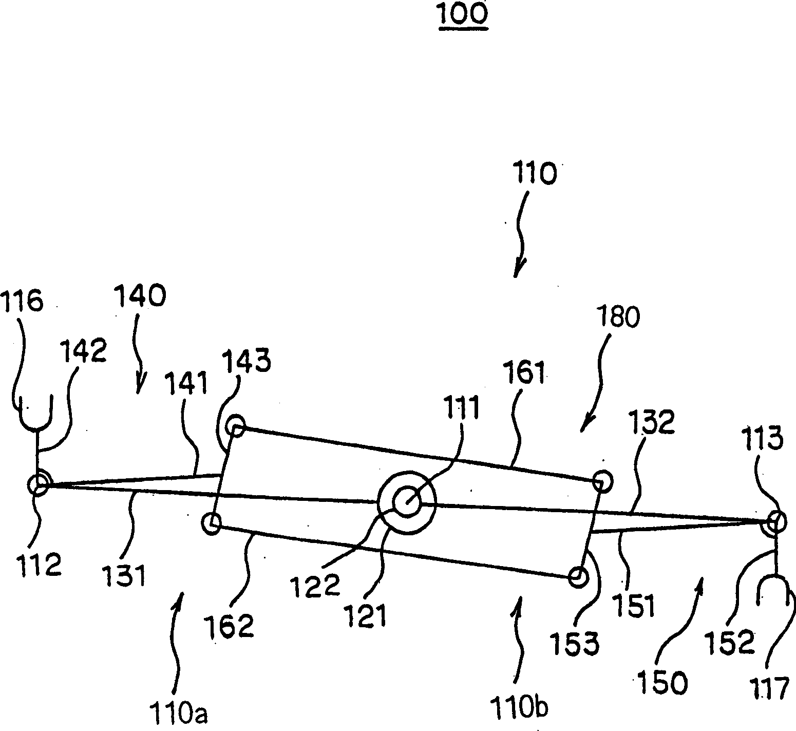
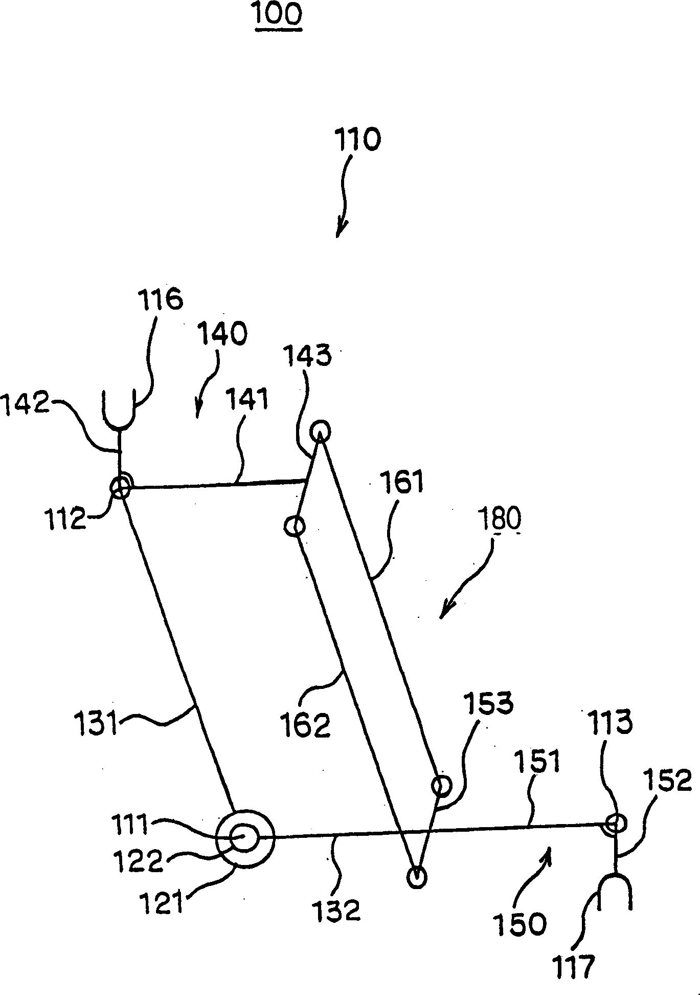
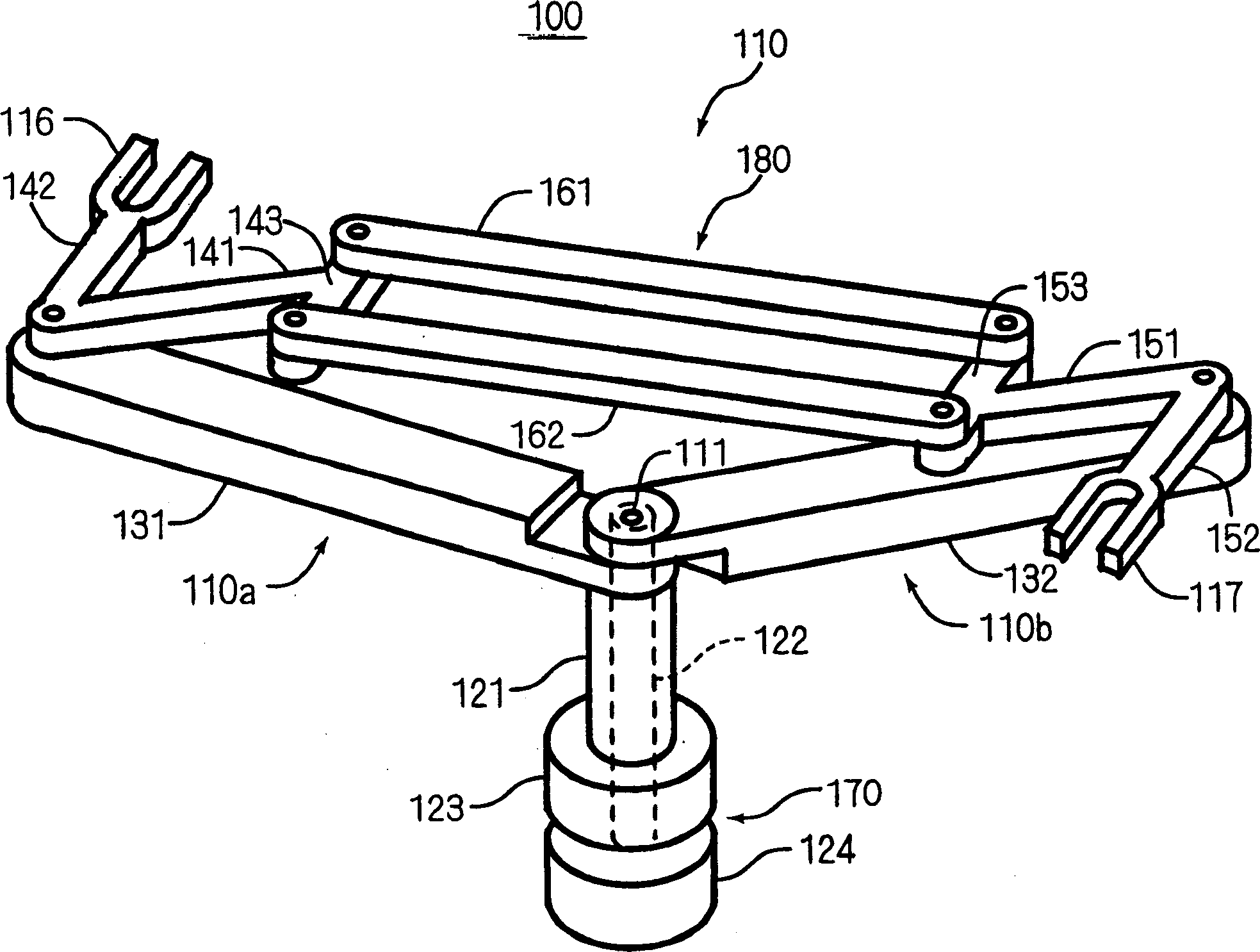
[0038] now refer to Figure 1-15 Embodiments of a robot arm mechanism and a robot device according to the present invention are described. Throughout the following detailed description, like reference symbols and numerals refer respectively to like parts throughout the drawings.

[0039] A first embodiment of a robot arm mechanism and a robot device according to the invention will be referred to in the appended Figure 1-5 be described first.

[0040] figure 1 and 2 The illustrated robotic arm mechanism 110 includes a first handling member 116 for supporting and handling a first object, and a second handling member 117 for supporting and handling a second object. The configuration of the first and second handling members 116 and 117 can be used for handling, ie, holding and releasing a wafer and other materials for producing semiconductors. The structures of the first and second manipulating parts 116 and 117 depend on the size and shape of the material processed by the f...


PUM


Abstract

Herein disclosed is a robot arm mechanism comprising a first handling member 116 for supporting and handling a first object; a second handling member 117 for supporting and handling a second object; a first robot arm 110a including a first arm link 131 and a second arm link 142, the first end portion of the second arm link 142 being pivotably connected to the second end portion of the first arm link 131, and the second end portion of the second arm link 142 being connected to the first handling member 116 to allow the first handling member 116 to support the first object in a stable condition; a second robot arm 110b including a first arm link 132 and a second arm link 152, the first end portion of the second arm link 152 being pivotably connected to the second end portion of the first arm link 132, the second arm link 152 being inclined with respect to the second arm link 142 of the first robot arm 110a at a preset angle defined between the central line of the second arm link 152 of the second robot arm 110b and the central line of the second arm link 142 of the first robot arm 110a, and the second end portion of the second arm link 152 being connected to the second handling member 117 to allow the second handling member 117 to support the second object in a stable condition; a robot arm moving mechanism for allowing one of the first arm links 131 and 132 of the first and second robot arms 110a and 110b to be angularly moved with respect to the other of the first arm links 131 and 132 of the first and second robot arms 110a to 110b; and an angle keeping mechanism for keeping substantially fixed the preset angle defined between the central line of the second arm link 152 of the second robot arm 110b and the central line of the second arm link 142 of the first robot arm 110a as one of the first arm links 131 and 132 of the first and second robot arms 110a and 110b is angularly moved with respect to the other of the first arm links 131 and 132 of the first and second robot arms 110a and 110b.

Description

technical field [0001] The present invention relates to a robotic arm mechanism capable of retracting and extending, and more particularly, the present invention relates to a robotic arm mechanism having an arm drive mechanism for driving the arm into retracted and extended positions. Background technique [0002] Hitherto, a variety of conventional robot arm mechanisms have been employed in the semiconductor production process, during which the robot arm mechanism is used to retract and extend the robot arm to manipulate a workpiece, ie, an object to be processed. These objects may include workpieces such as wafers and other precision parts, which are conveyed and unloaded on a table by a robotic arm mechanism. [0003] A typical example of this type of conventional robot arm mechanism is disclosed in, for example, Japanese Patent Laid-Open No. 2002-222488 and shown in FIG. 16 . The conventional robot arm mechanism 910 shown in FIG. 16 includes a first operating member 951...

Claims


Application Information

Patent Timeline
IPC IPC(8): B25J9/06B25J9/10B25J18/02H01L21/677
CPCY10S414/13B25J9/1065H01L21/67739Y10T74/20329B25J9/06
Inventor 森弘树渡边彻也奥野长平
Owner TEIJIN SEIKI CO LTD
Learn More