
Constant force device

A technology of constant force device and force balance, which is applied in the direction of instruments, clock drive mechanisms, escapement mechanisms, etc., and can solve the problems of unfavorable use of constant force devices alone

Inactive Publication Date: 2003-07-02
瑞士维拉尔苏尔格拉讷
View PDF1 Cites 18 Cited by
  • Summary
  • Abstract
  • Description
  • Claims
  • Application Information

AI Technical Summary

Problems solved by technology

Finally, the use of constant force devices alone is disadvantageous in cases where a combination with other devices designed to precisely regulate movement, such as Tourbillon mechanisms, would have sufficiently improved results

Method used


Image

  • Constant force device
  • Constant force device
  • Constant force device

Examples


Embodiment Construction

[0015] Embodiments of the device will be described in detail below with reference to the above-mentioned drawings.

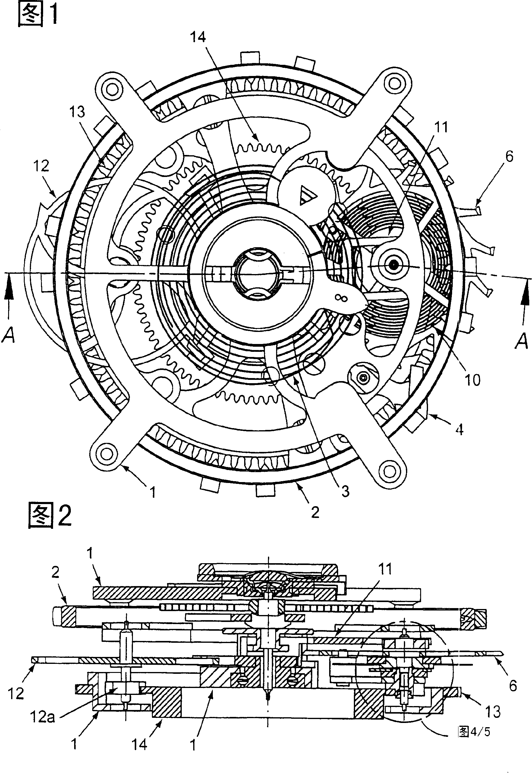
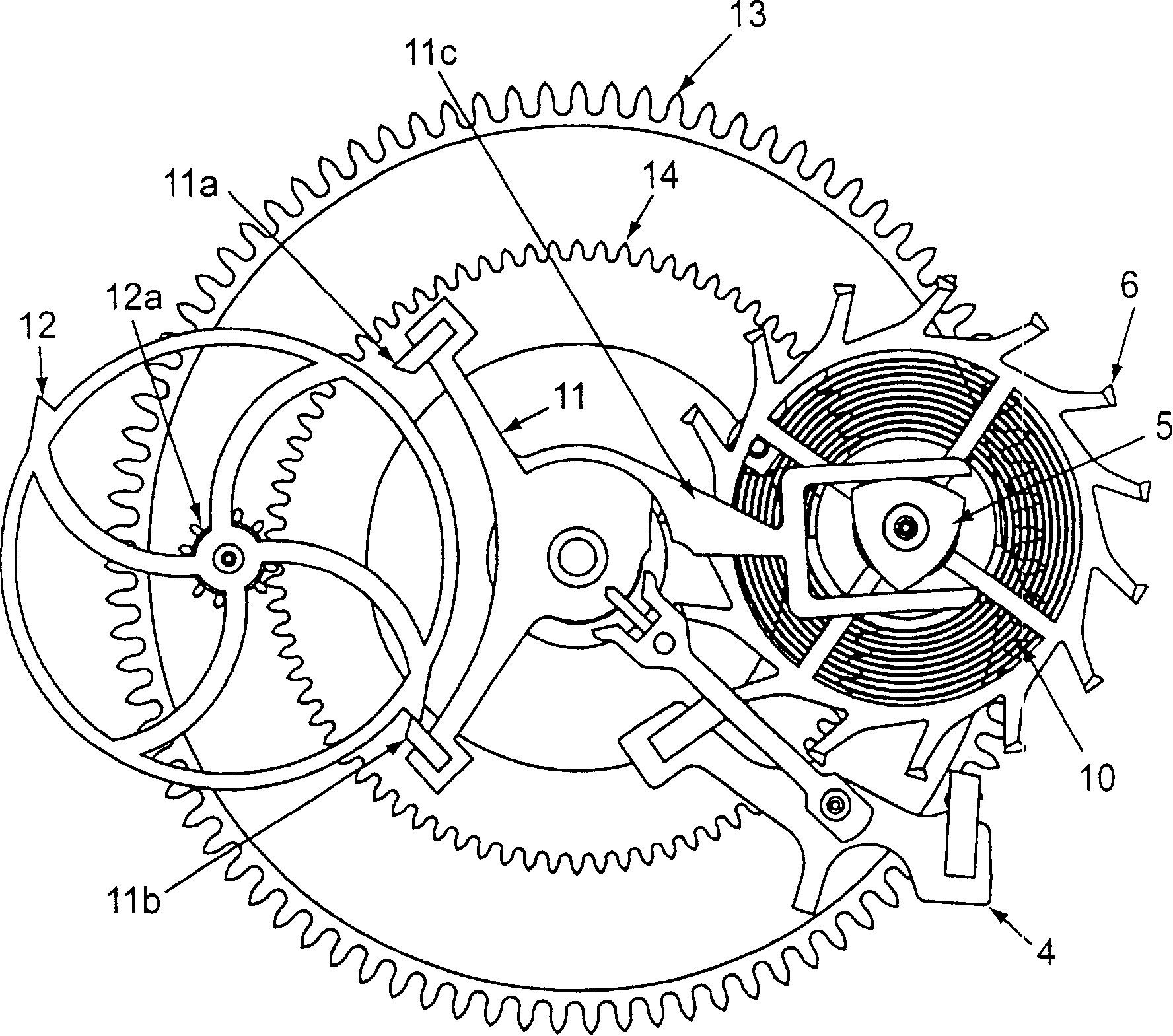
[0016] FIG. 1 shows a constant force device according to the invention integrated into a Tourbillon mechanism. The Tourbillon mechanism consists of a Tourbillon frame 1 with a balance wheel 2 rotatably mounted at its center; a helical spring 3; a drive gear 13; and a second fixed wheel 14 and in certain cases a second fixed The second fixed wheel, not shown, is concentric with the first second fixed wheel and has a different number of teeth and diameter.

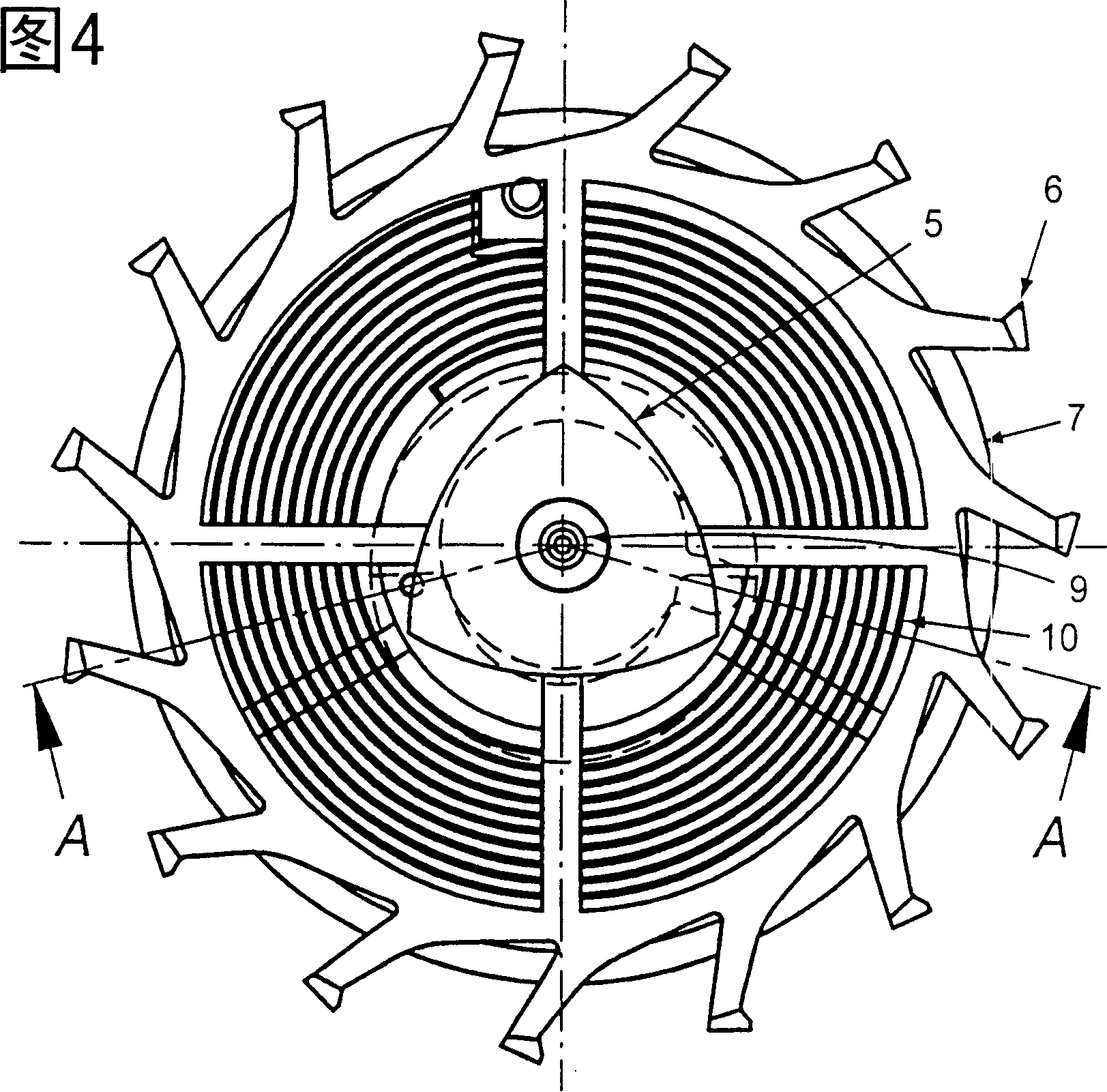
[0017] The fixed-seconds wheel 14 or, if present, the second fixed-seconds wheel engages the pinion 12a of the stop wheel, fixedly connected to the stop wheel 12 and mounted eccentrically and rotatably within the tourbillon carriage. In the described embodiment, this stop wheel 12 has two teeth that cooperate with the anchor fingers 11a and 11b of the second anchor 11 of the constant force device, which in th...


PUM


Abstract

The present invention relates to a constant-force device for precise regulation of mechanical watch movements by means of a uniform transmission of force from the escape wheel to the regulating organ of the watch, this device being adapted to be integrated into a Tourbillon mechanism.

Description

technical field [0001] The present invention relates to a constant force device for precise regulation of the movement of a mechanical watch by uniformly transmitting force from the escape wheel to the watch's regulating mechanism, suitable for integration into a Tourbillon in the institution. Background technique [0002] Constant force devices have been known for quite a long time, and are mostly implemented by means of an additional spring, which at any given moment has a certain amount of pretension, compensating for the apparent A variable driving force of the clockwork, and periodically retensioned by a specific amount. Although the tension is consumed to keep the watch's adjustment mechanism swinging, the transmitted force can be considered to be far more constant than if the adjustment mechanism were only driven by the main spring. [0003] The paper "Les remontoirs d'égalitéet les forces constantes dans la montre" by Messrs Y. Droz and J. Flores describes a consta...

Claims


Application Information

Patent Timeline
Patent Type & Authority Applications(China)
IPC IPC(8): G04B1/22G04B15/10G04B17/28
CPCG04B17/285G04B15/10
Inventor 让-弗朗索瓦·莫容
Owner 瑞士维拉尔苏尔格拉讷
Learn More