Dielectric barrier discharge lamp
A dielectric barrier and discharge lamp technology, applied in the direction of discharge lamps, gas discharge lamps, discharge tubes/lamps, etc., to achieve the effect of cheap glass welding
- Summary
- Abstract
- Description
- Claims
- Application Information
AI Technical Summary
Problems solved by technology
Method used
Image
Examples
Embodiment Construction
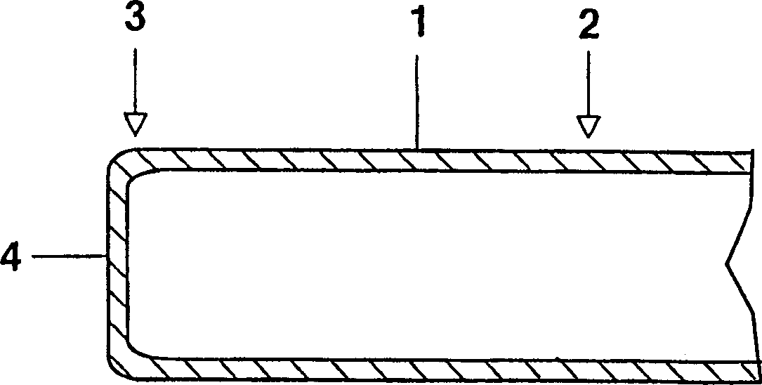
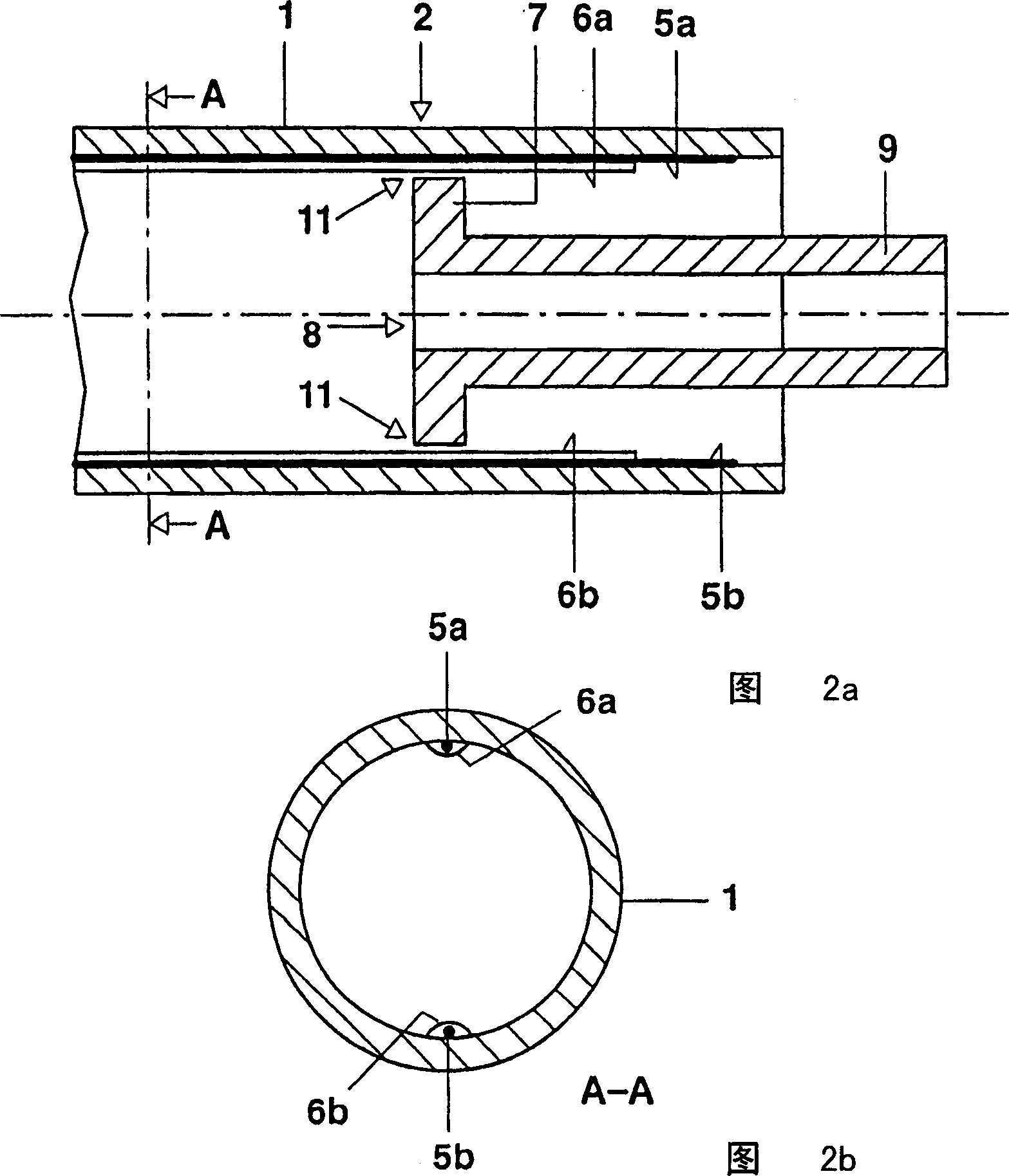
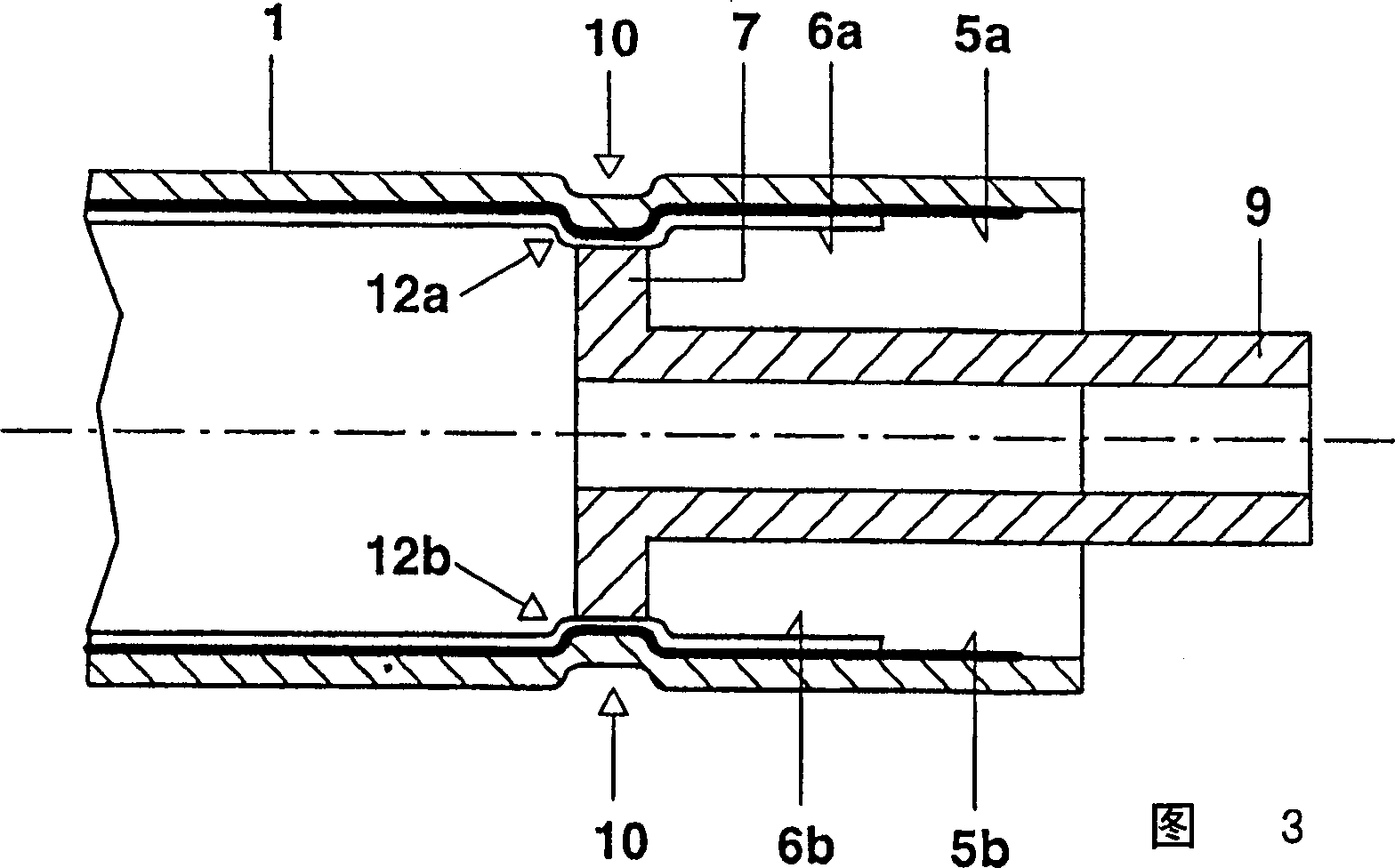
[0027] figure 1 to 3 are used to illustrate the dielectric barrier layer-discharge lamp manufacturing method of the present invention.
[0028] figure 1 A discharge vessel 1 made of soda-lime glass is shown, which is temporarily still open at a first end 2, but whose second end 3 has been sealed with a flat frit 4.
[0029] 2a, 2b respectively show a schematic longitudinal section of the open end 2 of the discharge vessel 1 and a schematic cross section along the section line A-A. The inner wall of the discharge vessel 1 has been provided with two radially arranged linear silver inner electrodes 5a, 5b which are each covered with a dielectric glass barrier layer 6a, 6b. Furthermore, a disc-shaped sealing element 7 has been arranged concentrically in the open end 2 of the discharge vessel 1 . The outer diameter of the disk-shaped sealing element 7 is slightly smaller than the inner diameter of the discharge vessel minus the thickness of the two inner electrodes 5a, 5b includ...
PUM
| Property | Measurement | Unit |
|---|---|---|
| Radial depth | aaaaa | aaaaa |
Abstract
Description
Claims
Application Information
 - R&D
- Intellectual Property
- Life Sciences
- Materials
- Tech Scout
- Unparalleled Data Quality
- Higher Quality Content
- 60% Fewer Hallucinations
Browse by: Latest US Patents, China's latest patents, Technical Efficacy Thesaurus, Application Domain, Technology Topic, Popular Technical Reports.
© 2025 PatSnap. All rights reserved.Legal|Privacy policy|Modern Slavery Act Transparency Statement|Sitemap|About US| Contact US: help@patsnap.com


