Device and method for controlling write-in data during generating error in optical drive

An optical drive, error technology, applied in the direction of recording/reproduction by optical method, optical recording/reproduction/erasing method, data recording, etc., capable of solving errors with narrow range, difficulty in handling them properly, and no execution of data writing And other issues

Inactive Publication Date: 2002-12-25
SAMSUNG ELECTRONICS CO LTD
View PDF0 Cites 5 Cited by
  • Summary
  • Abstract
  • Description
  • Claims
  • Application Information

AI Technical Summary

Problems solved by technology

Consequently, the range of errors that can be detected is narrow, making it difficult to properly handle errors due to factors other than buffer underruns
[0005] Also, in the case of the existing optical drive, when an error is detected, the writing mode is stopped and handled as a failure, but the operation of normally completing data writing is not performed

Method used


Image

  • Device and method for controlling write-in data during generating error in optical drive
  • Device and method for controlling write-in data during generating error in optical drive
  • Device and method for controlling write-in data during generating error in optical drive

Examples


Embodiment Construction

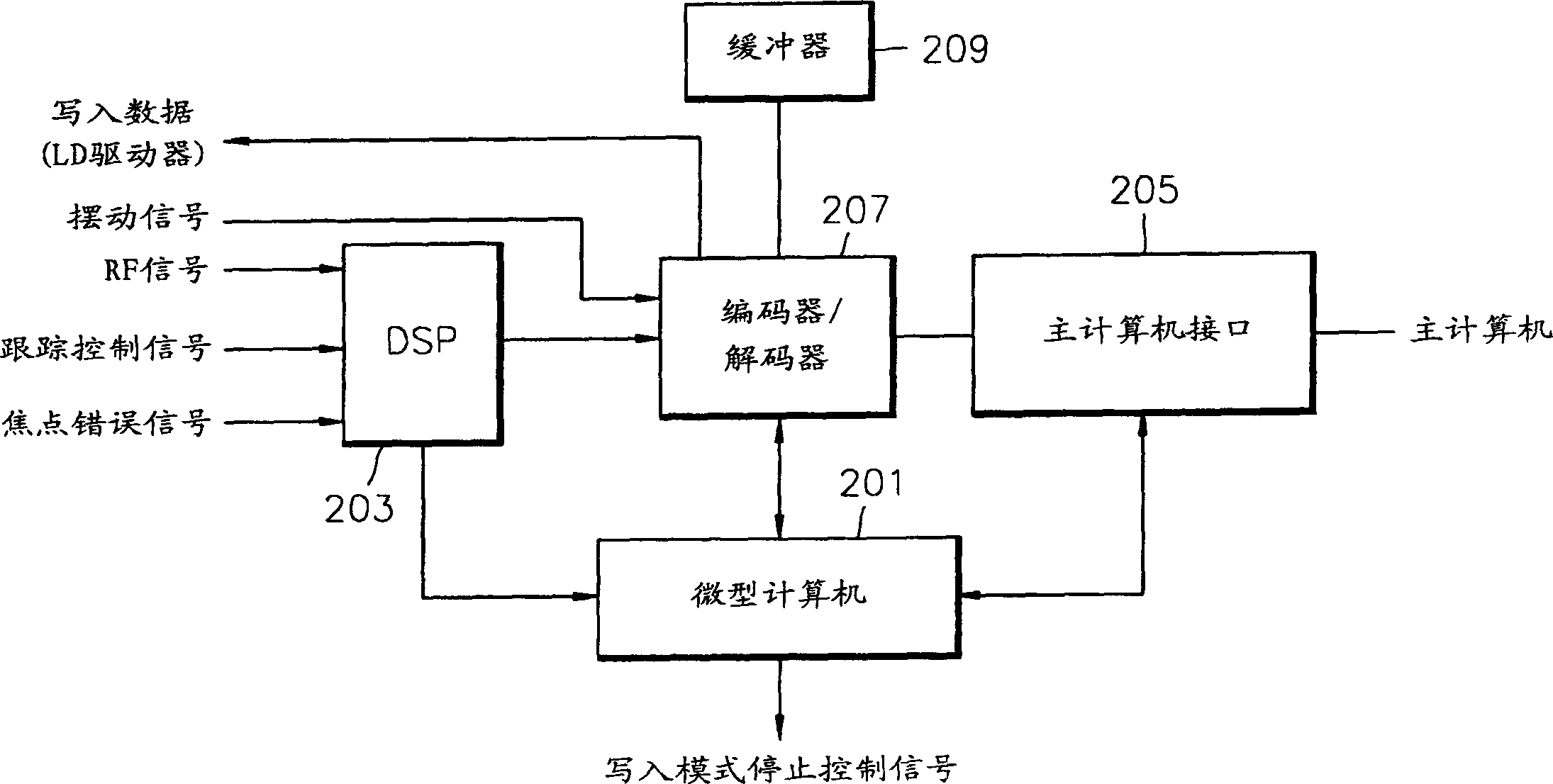
[0014] see figure 2 , an optical driver includes: a microcomputer 201 , a digital signal processor (DSP) 203 , a host computer interface 205 , an encoder / decoder 207 and a buffer 209 . The microcomputer 201 controls writing in the optical drive, and the DSP 203 provides servo signals so that the microcomputer 201 can detect errors in the optical drive in write mode. The host computer interface 205 connects a host computer (not shown) and the optical drive for data transmission between them. The encoder / decoder 207 stores data provided through the computer interface 205 in a buffer, encodes the data stored in the buffer 209 for transmission to an optical disc (not shown), and further decodes the data from an optical disc (not shown). output) reproduced and processed by the DSP 203 to send it to the host computer interface 205 and the microcomputer 201. Buffer 209 stores data provided by encoder / decoder 207 in write mode.

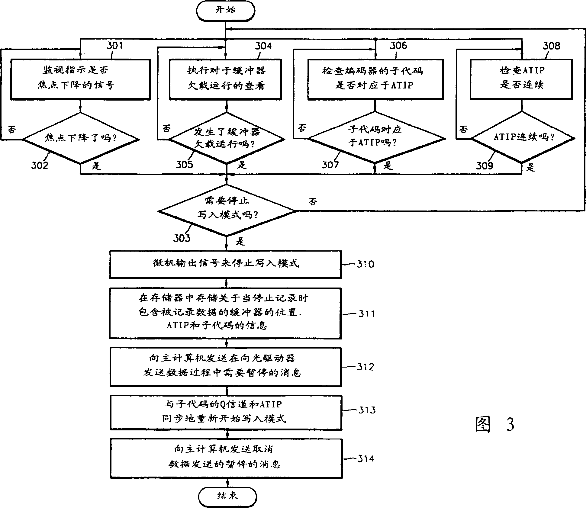
[0015] 3 is a flowchart for explaining a method of ...


PUM


Abstract

The present invention provides an apparatus and method for controlling the writing of data, which enable data writing to be restarted at the point where it was stopped, and enable data writing to be restarted by monitoring when data writing was stopped due to an error in write mode Buffer underrun and multiple servo signals to perform writes precisely. The method includes: monitoring an error when writing is performed; checking whether the write mode is stopped when an error is detected; resuming predetermined data required for writing the mode; and resuming writing with said predetermined data. Accordingly, errors can be detected by monitoring a plurality of servo signals as well as buffer underrun while performing a write function, thus enabling more precise control of the write mode operation.

Description

technical field [0001] The present invention relates to an optical drive, and in particular, to an apparatus and method for controlling writing data when an error occurs in the optical drive. Background technique [0002] Optical drives are used to record or reproduce data to or from optical discs such as CDs or DVDs. When an error occurs in the write mode in the optical drive, the write mode is stopped and handled as a failure, and then corrective action is taken. At this time, the occurrence of errors is checked by monitoring the buffer-under-run, which generally occurs when the amount of data stored in the buffer falls below a predetermined level. A buffer is included in the optical drive to store data provided by the host computer. [0003] figure 1 is a flowchart for explaining a conventional method of controlling writing data when an error occurs in an optical drive. see figure 1 , the optical drive is checked for buffer underrun in write...

Claims


Application Information

Patent Timeline
IPC IPC(8): G11B7/0037G11B7/0045G11B19/04G11B20/10G11B20/18G11B27/36
CPCG11B7/0037G11B7/0045G11B19/04G11B20/10527G11B20/18G11B27/36G11B2020/10814G11B2020/1269G11B2220/216G11B2220/218G11B2220/2545G11B2220/2562G11B2220/2575
Inventor 金周晔金垣
Owner SAMSUNG ELECTRONICS CO LTD
Why Eureka
Try Eureka