Screw holder with hook

A technology for holding devices and screws, applied in the direction of screws, nuts, bolts, etc., can solve complex and time-consuming problems

Inactive Publication Date: 2002-10-02
SHIMANO INC
View PDF0 Cites 1 Cited by
  • Summary
  • Abstract
  • Description
  • Claims
  • Application Information

AI Technical Summary

Problems solved by technology

[0004] Known methods of holding screws in a stationary position are complex and time consuming

Method used


Image

  • Screw holder with hook
  • Screw holder with hook
  • Screw holder with hook

Examples


Embodiment Construction

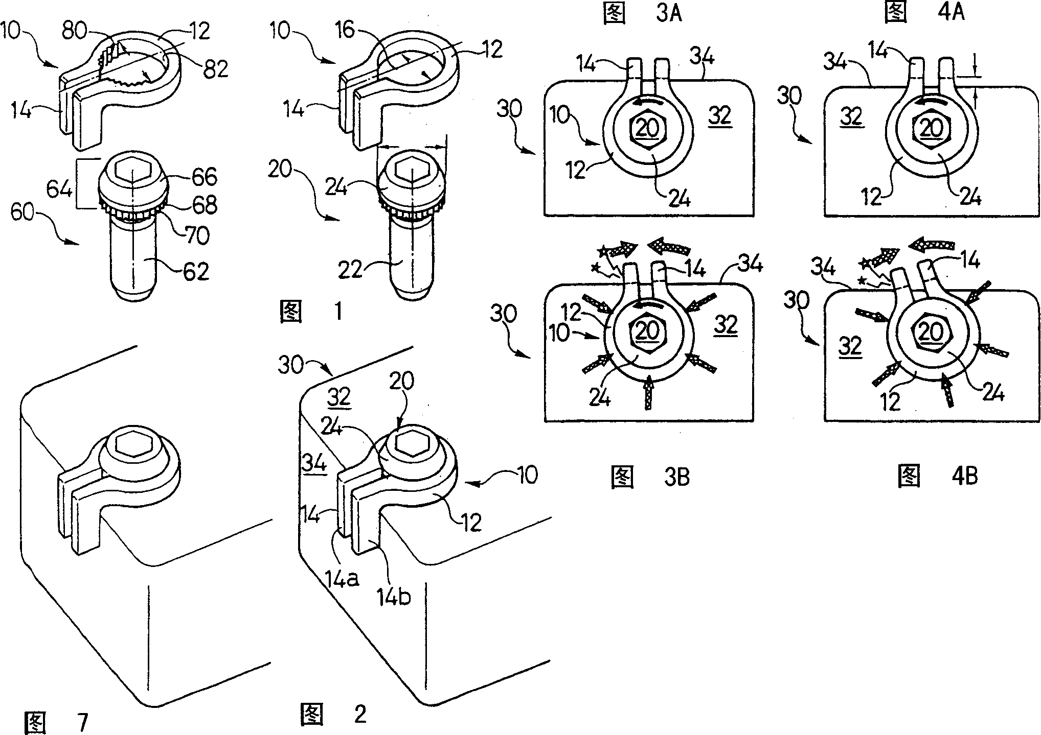
[0023] A preferred embodiment of the screw holding device according to the invention is shown in FIG. 1 , indicated by numeral 10 . The screw holder 10 has a clamping part 12 and a hook part 14 . In a preferred embodiment of the invention, the hook portion 14 lies in a plane substantially perpendicular to the plane of the gripping portion 12 . The clamping portion 12 of the screw holding device 10 defines a cutout 16 therein. The cutout 16 is preferably sized to receive the screw 20 and securely retain the screw 20 within the cutout 16 .

[0024] The screw retaining device 10 is configured for use with known screws, as well as special screws which will be described in detail below. As shown in FIG. 1 , screw 20 generally includes a shank 22 and a head 24 . In a preferred embodiment of the invention, the inner diameter 18 of the clamping portion 12 of the screw retaining device 10 is smaller than the outer diameter 26 of the head 24 of the screw 20 . The retaining device 10...


PUM


Abstract

The invention discloses a screw holding device with a clamping part and a hook part. The clamping portion engages the screw head to hold the screw securely. The hook interacts with the surface of the element to which the screw is fastened to limit the rotation of the screw. The screw retaining device is configured for use with any known screw having a protruding head. In a preferred embodiment of the invention, the screw retaining device is used with a serrated screw, wherein the clamping portion of the screw retaining device includes a serrated portion which corresponds to and engages the serrations on the serrated screw to securely clamp Hold the screw.

Description

technical field [0001] FIELD OF THE INVENTION The present invention relates generally to screw retaining devices, and more particularly to screw retaining devices having clamping portions for securely gripping a screw and hook portions for positioning the screw. Background technique [0002] When using fasteners such as screws, there is a risk that vibration or other conditions will cause the screws to shift, loosen and in some cases fall out. Numerous screw retention devices and methods have been developed to prevent loosening or falling out of screws. As shown in Fig. 9, a disclosed known device 100 is used to prevent falling out. Apparatus 100 includes a wire binding mechanism 102 for wire binding a pair of tightened screw heads 104, 106 together. [0003] Another known device 120 is shown in Figures 10A-10C. As best shown in FIG. 10A , the known device 120 includes a fastening plate 122 having a pair of holes 124 sized to receive screws 126 . As...

Claims


Application Information

Patent Timeline
Patent Type & Authority Applications(China)
IPC IPC(8): F16B39/02F16B39/10
CPCF16B39/108
Inventor 名合大辅
Owner SHIMANO INC
Why Eureka
Try Eureka