
System and method for recovering symbol timing offset and carrier frequency error

A carrier frequency and symbol timing technology, applied in the field of digital communication, which can solve the problems of not providing the best synchronization results, unable to overcome the influence of signal propagation, and unable to fully enhance the correlation peak signal-to-noise ratio.

Inactive Publication Date: 2002-05-29
IBIQUITY DIGITAL CORP
View PDF42 Cites 6 Cited by
  • Summary
  • Abstract
  • Description
  • Claims
  • Application Information

AI Technical Summary

Problems solved by technology

However, its relatively flat amplitude profile requires separate integration prior to its peak detection
[0004] The simplistic signal processing in Suzuki's patent, that is, only integrating the correlation peak before its detection, cannot provide the best synchronization result. The reason is the following two aspects. First, when increasing the number of frequency carriers in a multicarrier signal, due The effect of adjacent noise, correlation peaks become indistinct, and mere integration does not sufficiently enhance the signal-to-noise ratio of pre-detected correlation peaks
Second, integration alone does not overcome well known signal propagation effects such as scatter, correlation peaks
Second, integration alone does not overcome well-known signal propagation effects such as scattering, fading, or other signal interference, all of which combine to cause signal loss and false peaks

Method used


Image

  • System and method for recovering symbol timing offset and carrier frequency error
  • System and method for recovering symbol timing offset and carrier frequency error
  • System and method for recovering symbol timing offset and carrier frequency error

Examples


Embodiment Construction

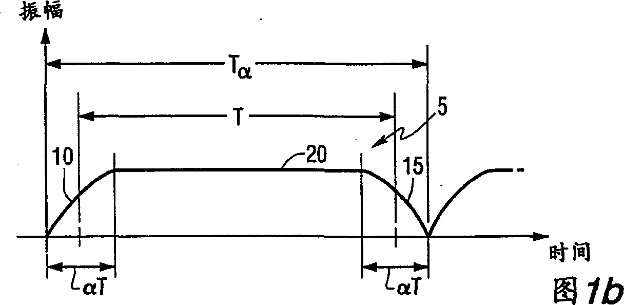
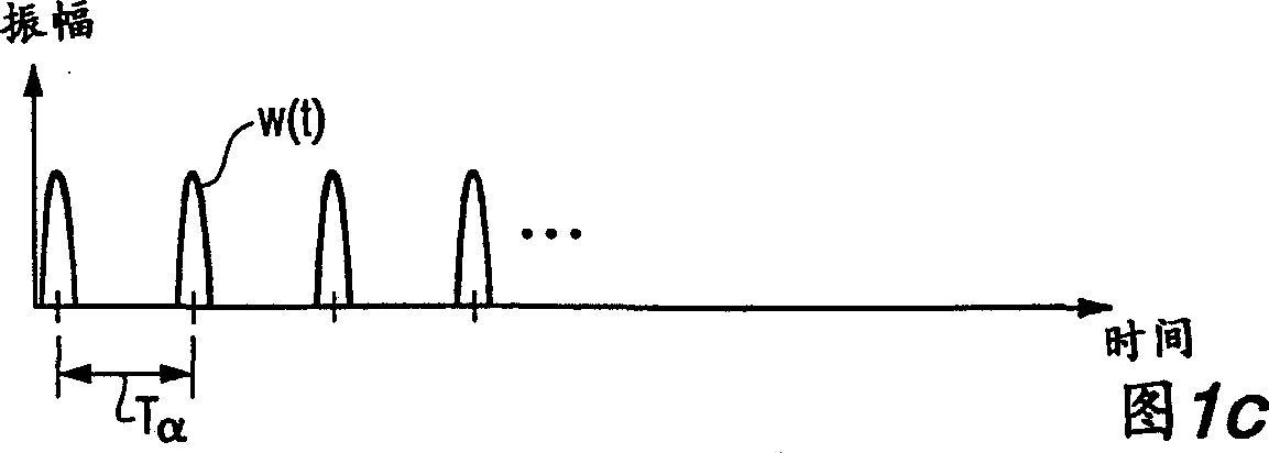
[0031] In a digital communication transmission reception scheme in which a stream of digitally modulated information carrying a signal is transmitted to a receiver, where the symbols are then demodulated to recover the transmitted information, only if the transmitted symbol timing and phase / phase can be determined at the receiver frequency for the receiver demodulator to successfully and optimally demodulate the symbols. Therefore, the receiver must obtain or recover the received symbol timing and carrier phase / frequency, which will be utilized by the demodulation process, before successfully demodulating the received symbols. Once the received symbol timing and frequency are recovered at the receiver, and demodulation of the symbols is thereafter initiated, the symbol timing and carrier frequency can be tracked using a servo loop to maintain the integrity of the demodulation process. It is an object of the system or architecture of the present invention to transmit a series o...


PUM


Abstract

The system for recovering symbol timing offset and carrier frequency error from an orthogonal frequency division multiplexed (OFDM) signal includes a receiver circuit for receiving an OFDM modulated signal representing a series of OFDM symbols, and providing a received signal to an output thereof. A peak development circuit is included for developing a signal having a plurality of signal peaks representing symbol boundary positions for each received OFDM symbol, where each of the signal peaks is developed responsive to an amplitude and phase correspondence produced between the leading and trailing portions of each of the received OFDM symbols. The system includes a circuit for enhancing the signal peak detectability, which includes a circuit for additively superimposing and then filtering the signal peaks, to produce an enhanced signal peak having an improved signal-to-noise ratio. A circuit for establishing a temporal position indicative of the symbol boundary position from at least one of the enhanced signal peaks output from the signal enhancing module is also provided. Further, a circuit for recovering the received OFDM signal carrier frequency error corresponding to the temporal position is included.

Description

technical field [0001] The present invention relates to the field of digital communication, more precisely, the object of the present invention is a system for obtaining or recovering symbol timing offset and carrier frequency error from digitally modulated multi-carrier communication signals. The invention is also directed to a diversity system for recovering signal timing offsets and carrier frequency errors from different multi-frequency digitally modulated signals. technical background [0002] In digital communication systems, signal synchronization between the transmitter and receiver must be achieved before effective signal demodulation can begin at the receiver. Accordingly, in existing digital communication techniques, attempts have been made to develop systems most suitable for recovering or acquiring received signal timing and carrier frequency. [0003] Petitioner's US Patent No. 5,541,552 to Suzuki provides an attempt to demodulate digitally modulated multi-car...

Claims


Application Information

Patent Timeline
Patent Type & Authority Applications(China)
IPC IPC(8): H04L27/22H04L27/26
CPCH04L27/2676H04L27/2662H04L27/2657H04L27/26
Inventor 保尔·詹姆斯·佩拉约瑟夫·伯特拉姆·布朗德
Owner IBIQUITY DIGITAL CORP
Learn More