Breaking switch provided with fuse

A technology of breaking switches and fuses, which is applied in the direction of emergency protection devices, circuits, electrical components, etc., and can solve the problems that the reliability cannot meet the requirements of telecommunication systems, etc.

Inactive Publication Date: 2002-02-06
EATON INTELLIGENT POWER LIMITED
View PDF0 Cites 0 Cited by
  • Summary
  • Abstract
  • Description
  • Claims
  • Application Information

AI Technical Summary

Problems solved by technology

The reliability of the conventional fuse state identification mechanism cannot meet the requirements of the telecommunication system
[0005] For at least the reasons mentioned above, the use of known fused switch disconnectors has not been fully satisfactory for certain applications, such as in telecommunications systems

Method used


Image

  • Breaking switch provided with fuse
  • Breaking switch provided with fuse
  • Breaking switch provided with fuse

Examples


Embodiment Construction

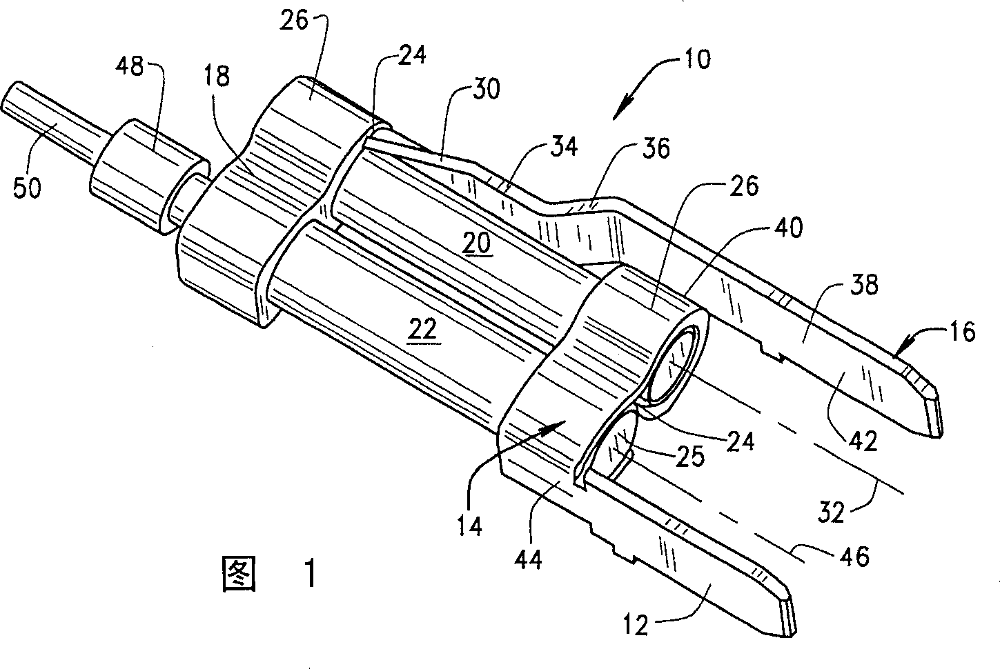
[0015] 1 is a plan view of a fuse terminal assembly 10 including a load side termination blade 12 extending from a lower fuse carrier 14 and a line side termination blade 16 extending from an upper fuse carrier 18 . The terminating blades 12, 16 and the fuse holders 14, 18 are integrally formed of conductive material and are electrically connected by a primary fuse 20 and a secondary fuse 22 as a fuse status indicator. A primary fuse 20 and a secondary fuse 22 extend between the upper and lower fuse brackets 14 , 18 and are held in parallel between the terminating blades 12 and 16 . Fuse blades 14 , 18 are configured to receive cylindrical conductive end cap 24 of primary fuse 20 and conductive end cap 25 of secondary fuse status indicator 22 . The secondary fuse 22 has a much higher resistance than the primary fuse 20 so that when the line-side and load-side terminals 16, 12, respectively, are connected into a circuit (not shown), substantially All the currents pass through ...


PUM


Abstract

A fused disconnect switch assembly includes a switch housing assembly and a pull out fuse assembly. The switch housing assembly includes a housing defining a fuse receptacle, first and second terminal contacts within the housing and located adjacent the fuse receptacle, and an alarm terminal extending from the fuse receptacle to an exterior of the fuse housing. The pull out fuse assembly includes a housing, a line side terminal extending from the housing, a load side terminal extending from the housing, and a primary fuse having first and second conductive end caps. The fuse end caps are coupled to respective line side and load side terminals of the pull out fuse assembly housing, and the first and seco nd terminal contacts of the switch housing assembly receive the load side and the line side terminal blades of the pull out fuse assembly.

Description

technical field [0001] The present invention relates to a disconnect switch, and more particularly, to a disconnect switch equipped with a fuse. Background technique [0002] Fuses are also widely used in overcurrent protection devices to prevent severe damage to electrical circuits. A fuse terminal generally forms an electrical connection between a power source and an electrical component or combination of electrical components in an electrical circuit. One or more fusible links or fuse element devices are connected between the fuse terminals so that when the current through the fuse exceeds a predetermined limit, the fusible element melts, thereby opening one or more through Fuses in a circuit, thereby preventing electrical components from being destroyed. [0003] In some applications, fuses are used not only to provide fused electrical connections, but also for connecting and breaking or switching purposes, for making or breaking one or several electrical connections...

Claims


Application Information

Patent Timeline
IPC IPC(8): H01H85/30H01H85/32H01H85/54
CPCH01H85/303H01H85/547H01H85/306H01H85/32
Inventor R·E·莫勒特B·C·霍尔
Owner EATON INTELLIGENT POWER LIMITED
Why Eureka
Try Eureka