Optical cable laying and fiber distributing method for optical fiber to house

A fiber optic cable laying and branching technology, applied in the direction of fiber optic/cable installation, etc., can solve the problems of high cost and troublesome construction, and achieve the effect of fewer optical cables, simple construction and laying, and reduced cable consumption

Active Publication Date: 2007-08-22
WUHAN YANGTZE OPTICAL TECH
View PDF5 Cites 0 Cited by
  • Summary
  • Abstract
  • Description
  • Claims
  • Application Information

AI Technical Summary

Problems solved by technology

[0003] There are also optical fiber splitters for branch connection, but the cost of laying is high and the construction is troublesome

Method used


Image

  • Optical cable laying and fiber distributing method for optical fiber to house
  • Optical cable laying and fiber distributing method for optical fiber to house

Examples


Embodiment Construction

[0014] Embodiments of the present invention will be further described below in conjunction with the accompanying drawings.

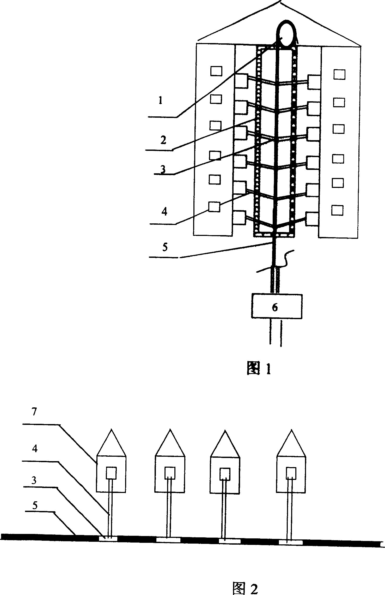
[0015] The first embodiment, as shown in Figures 1 and 3, is used for the access of the shaft corridor 2, and adopts a skeleton type optical fiber ribbon cable 5 with 3 to 9 fiber ribbon grooves, commonly used as 3, 5, 6 or 8 Skeleton optical fiber ribbon cable with a fiber ribbon slot, and a branch window 3 is set on each layer of the skeleton optical fiber ribbon cable. The axial length of the branch window is 40-70mm, that is, the outer sheath of the optical cable is completely stripped by 40-70mm to form a branch Window, from the cable core of the branch window, draw out the branched fiber ribbon 8 from the forward extension section, that is, each branch window cuts off the fiber ribbon that needs to be branched through the preceding branch window that extends forward, and draws it out from the branch window A length of optical fiber ribbon is used a...


PUM


Abstract

The method of distributing fibers to doors adopts skeletal flat optical cable with branching windows connected to optical cable joint box for withdrawing branching fiber band and converting into tail fiber to door. The cable core in the skeletal flat optical cable has no filled ointment for easy to construction, the skeletal flat optical cable can hold more fibers, and each optical cable may have several branching windows in different axial positions. The present invention has greatly reduced cable consumption, easy construction and low cost, and is favorable to distributing fibers to doors.

Description

technical field [0001] The invention relates to a method for laying and distributing optical cables for fiber-to-the-home optical cables by adopting a skeleton type optical fiber ribbon optical cable. Background technique [0002] With the rapid development of communication technology and industry, optical fiber transmission has gradually expanded from medium and long-distance transmission to short-distance fiber-to-the-home. Most of the existing fiber-to-the-home optical cable laying and fiber distribution methods use tight-buffered optical cables and ordinary loose-tube stranded optical cables. When it is necessary to diverge the incoming optical fibers, it is impossible to create a separation window, so the optical cables can only be cut for splicing or laying and connecting multiple fibers at the same time. Optical cable, not only the design is complicated, the consumption of optical cable is large, the pipeline space occupied when laying is large, and a large number of ...

Claims


Application Information

Patent Timeline
Patent Type & Authority Patents(China)
IPC IPC(8): G02B6/46
Inventor 刘为罗中平蔡丹许定昉顾立新
Owner WUHAN YANGTZE OPTICAL TECH
Why Eureka
Try Eureka