Ring-shape cabling optical fiber laying method for fiber-to-the-home

A technology of divergence and optical fiber, applied in the direction of optical fiber/cable installation, etc., can solve the problems of troublesome construction and high cost, and achieve the effect of easy construction and laying, less optical cables, and easy construction.

Active Publication Date: 2008-01-09
WUHAN YANGTZE OPTICAL TECH
View PDF6 Cites 0 Cited by
  • Summary
  • Abstract
  • Description
  • Claims
  • Application Information

AI Technical Summary

Problems solved by technology

[0003] There are also optical fiber splitters for branch connection, but the cost of laying is high and the construction is troublesome

Method used


Image

  • Ring-shape cabling optical fiber laying method for fiber-to-the-home

Examples


Embodiment Construction

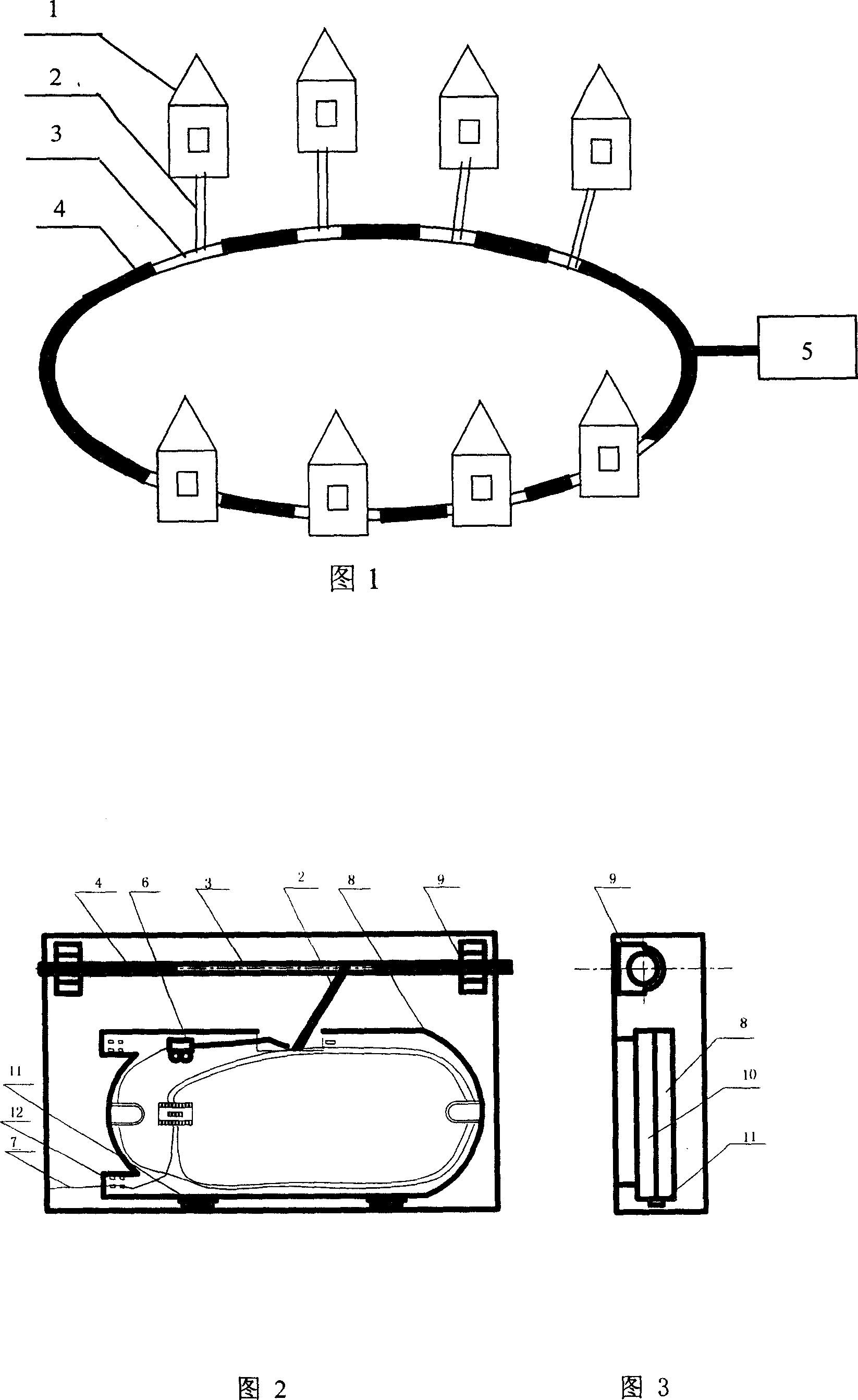
[0014] Embodiments of the present invention will be further described below in conjunction with the accompanying drawings.

[0015] An embodiment of the present invention is shown in Figures 1, 2, and 3. It is used for the access of users in flat-layout houses, and adopts skeleton optical fiber ribbon cables with 4 to 8 fiber ribbon slots. The skeleton optical fiber ribbon cables 4 are installed in each house User 1 opens branch window 3, the axial length of the branch window is 40-80mm, that is, the outer sheath of the optical cable is stripped by 40-80mm to form a branch window, and the branch is drawn out from the forward extension section in the cable core of the branch window The optical fiber ribbon 2 is cut off at the front branching window, and the cut optical fiber ribbon is drawn out from the branching windows on both sides of the adjacent two sides as a continuous branching optical fiber. The optical fiber ribbon can be 4 cores or 6 cores, and can be converted into ...


PUM


Abstract

This invention relates to fiber to household ring cabling branch distribution method, which adopts skeleton fiber band cable and is opened with branch window connected to the sub-connector and leads out branch fiber band from the branch window cable core. The fiber band is converted into tail fiber into household through sub-connector. The said skeleton fiber band is cable around user ring with tail fiber collected into one area. The branch fiber band is cut off into front and back branch windows with each fiber band collected into one area.

Description

technical field [0001] The invention relates to a ring laying and branching fiber distribution method for fiber-to-the-home by adopting a skeleton optical fiber ribbon cable. Background technique [0002] With the rapid development of communication technology and industry, optical fiber transmission has gradually expanded from medium and long-distance transmission to short-distance fiber-to-the-home. Most of the existing fiber-to-the-home cable laying and fiber distribution methods use tight-buffered optical cables and ordinary loose-tube stranded optical cables. When it is necessary to branch into the home optical fiber, it is impossible to create a separation window, so the optical cable can only be cut for splicing or laying and connecting multiple fibers at the same time. Optical cable, not only the design is complicated, the consumption of optical cable is large, the pipeline space occupied when laying is large, and a large number of cables are crowded, the divergence c...

Claims


Application Information

Patent Timeline
Patent Type & Authority Patents(China)
IPC IPC(8): G02B6/46
Inventor 刘为罗中平蔡丹许定昉皮亚斌
Owner WUHAN YANGTZE OPTICAL TECH
Why Eureka
Try Eureka