Method and apparatus for testing flash detector probe

A technology of scintillation detector and testing method, which is applied in the field of nuclear physics, and can solve the problems of large adhesive force and loss of the interface coupling glue between the crystal and the photomultiplier tube, and the inconvenient replacement of the photomultiplier tube or crystal.

Inactive Publication Date: 2007-07-25
ZIJINSHAN ASTRONOMICAL OBSERVATORY CHINESE ACAD OF SCI
View PDF4 Cites 0 Cited by
  • Summary
  • Abstract
  • Description
  • Claims
  • Application Information

AI Technical Summary

Problems solved by technology

The traditional method is to install the crystal and the photomultiplier tube in a metal container with elastic glue. After the parts are sealed, add an appropriate amount of photocoupling glue on the surface where the photomultiplier tube is connected. The components are connected by mechanical methods. The disadvantage of this traditional assembly and testing method is that it is not easy to replace the photomultiplier tube or crystal after it fails during the test, and it can only be scrapped together with the metal container because of the coupling strength of the elastic glue. Larger, cannot separate the photomultiplier tube or crystal from the metal container
[0004] Secondly; due to the strong adhesion of the interface coupling glue between the crystal and the photomultiplier tube, to separate the two parts, only a metal instrument with a thinner end can be used to forcefully pry at the interface, which will often damage one of the parts and cause economical damage. loss

Method used


Image

  • Method and apparatus for testing flash detector probe

Examples


Embodiment 1

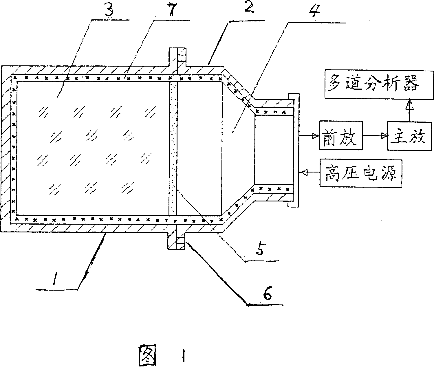
[0015] Embodiment 1, with reference to Fig. 1:

[0016] The scintillation detector probe is provided with an airtight dark gate. The dark box is composed of a scintillator container 1 and a photomultiplier tube container 2 tightly together. A scintillator 3 and a photomultiplier tube 4 are respectively arranged in the container, and there As the photocoupling glue 5 of the photoconductive material, there is an elastic glue 7 between the two and the container. Add 2 to 4 threaded through holes 6 at the end face of the metal container for encapsulating the photomultiplier tube or the end face of the metal container for encapsulating the crystal. The structure specially used for detection is: no elastic glue is used between the photomultiplier tube 5 and the container 2, but a soft solid material is used to plug tightly, and the high-voltage lead wire is sealed with vacuum black mud. The detection and assembly method includes the following steps:


PUM


Abstract

The present invention relates to experiment technology in nuclear physics field, and is the detection method and new structure of scintillation detector probe. The installation process includes the following steps: installing multiplier phototube inside a container, fastening with soft material, sealing with vacuum sealing material in the high voltage leads and detecting multiplier phototube; selecting proper crystal and multiplier phototube completing pre-detecting; and packing crystal and multiplier phototube with elastic adhesive and connecting electronic circuit. The new structure of the probe has 2-4 screw holes in the end plane of the metal container for the multiplier phototube or the crystal. The present invention can avoid damage of probe during disassembling.

Description

technical field [0001] The invention relates to an experimental technique in the field of nuclear physics, in particular to a test method of a scintillation detector probe and the structure of the scintillation detector probe used in the test method. Background technique [0002] In the field of nuclear physics, experimental technology actually includes three aspects, namely accelerator technology, reactor technology and detector technology, which constitute a complete set of nuclear physics experimental technology. Among them, detector technology usually includes three aspects: experimental equipment, detection method and data processing method. Experimental instruments refer to different types of detector principles, structures, types, performances, applications, etc. A detector currently used in our work is called a scintillation detector. The detector is composed of a probe, a high-voltage power supply, a preamplifier, a main amplifier, a pulse height analyzer, and a sc...

Claims


Application Information

Patent Timeline
Patent Type & Authority Patents(China)
IPC IPC(8): G01T1/202G01T1/208
Inventor 宫一忠王楠森张仁健唐和森张南常进舒双宝马涛于敏毛建萍
Owner ZIJINSHAN ASTRONOMICAL OBSERVATORY CHINESE ACAD OF SCI
Why Eureka
Try Eureka