Foot controlled speed changing device for bicycle

A speed change device and bicycle technology, applied in the direction of bicycle gear speed change mechanism, bicycle accessories, vehicle gearbox, etc., can solve the problems that the speed change ratio cannot be changed too much, the operation is not convenient enough, the speed change ratio is small, etc., to achieve speed change Large speed ratio, easy installation and reliable operation

Inactive Publication Date: 2006-11-01
罗明端
View PDF0 Cites 2 Cited by
  • Summary
  • Abstract
  • Description
  • Claims
  • Application Information

AI Technical Summary

Problems solved by technology

The current popular chain drive speed change device has the following defects: the speed change ratio cannot be changed too much, although some speed change devices have as many as ten or more gears, but to change from the fastest to the slowest speed, you must go through a multi-stage sprocket. The speed change can only be realized through step-by-step transition, and the speed ratio of the speed change is small; the chain and the sprocket are frequently switched during the speed change process, and the fault of the chain detaching from the sprocket is prone to occur; the speed change is manually operated, and accessories such as a speed change cable need to be installed, and the operation is not enough. convenient

Method used


Image

  • Foot controlled speed changing device for bicycle
  • Foot controlled speed changing device for bicycle
  • Foot controlled speed changing device for bicycle

Examples


Embodiment Construction

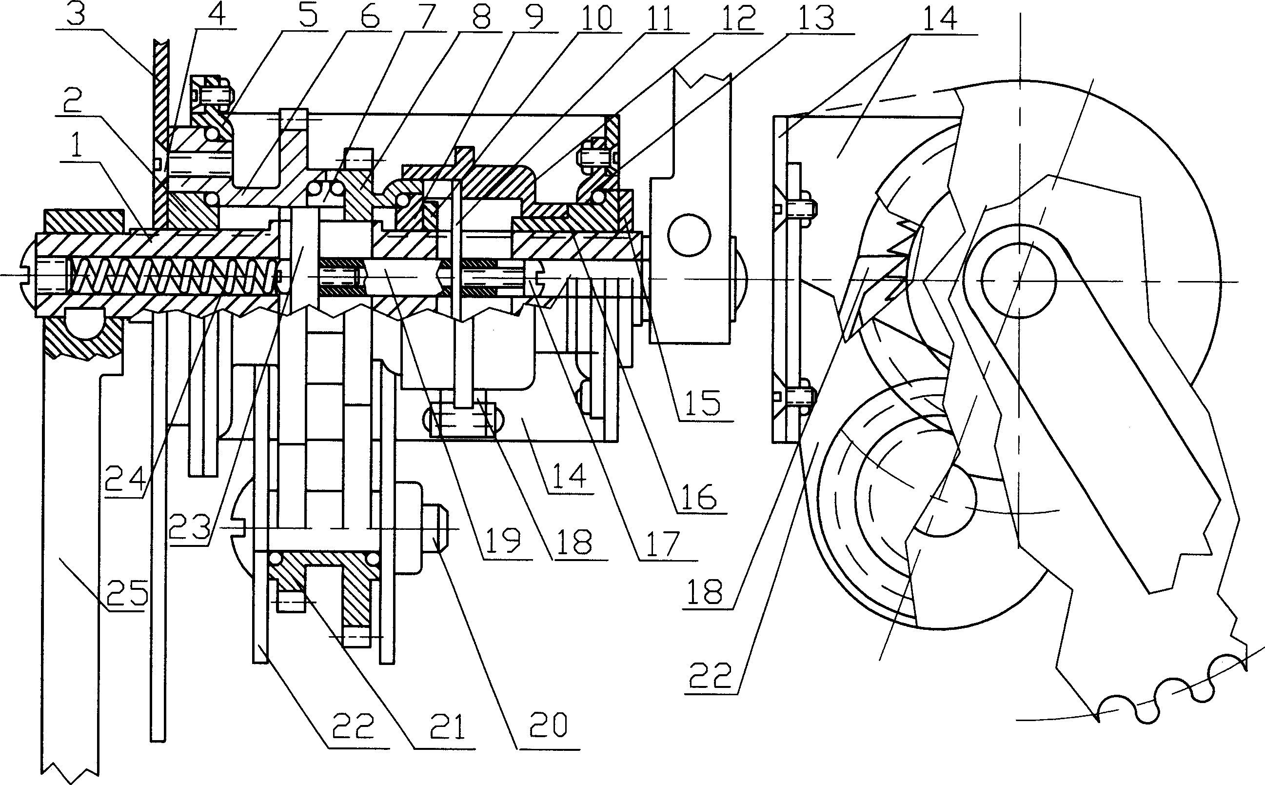
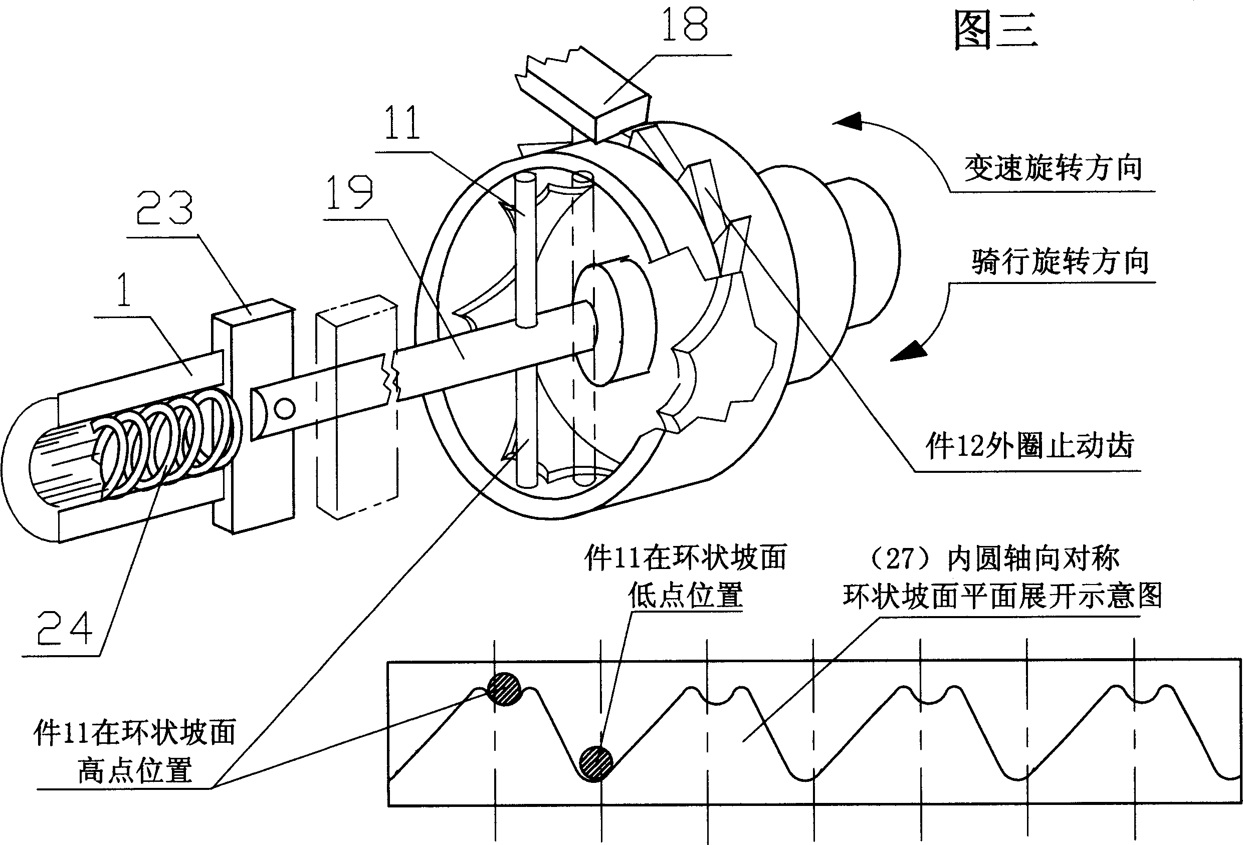
[0016] Referring to accompanying drawings 2 and 3, the central shaft 1 of the sprocket is a hollow shaft with an axial inner hole, and there is a long radial groove in the middle, and a rectangular key 23 is arranged in the groove, and the rectangular key 23 is exposed from the groove The outer two ends are stuck in the spline teeth of the inner diameter of the left fast gear 6, which drives the left fast gear 6 to rotate synchronously; the end face of the fast gear 6 is connected with the sprocket 3, and the gears 6 and 8 are jointly connected with the driven gear of the coaxial joint structure. The gear 21 meshes, the sprocket center shaft 1 is equipped with ball retaining rings 2, 9 and lock nuts 10, the gears 6, 8 are positioned on the sprocket center shaft 1, and the end face of the left fast gear 6 is fastened by a connecting screw 4 The sprocket 3 drives the rotation of the sprocket 3, thereby driving the chain and driving the wheels to rotate. The above process is the r...


PUM


Abstract

The invention relates to a pedal-controlled speed change device for a bicycle. The middle shaft of the sprocket (1) is provided with an axial inner hole and a radially through long groove, and a left-end fast gear (6) and a right-end slow gear (8) are coaxially installed. And speed change sleeve (12), left end fast gear (6), right end slow gear (8) are provided with inner diameter spline teeth, sprocket wheel (3) is connected with the end face of left end fast gear (6), sprocket wheel axis ( 1) The driven gear (21) with a coaxial conjoined structure is installed at the bottom, and its tooth surface meshes with the fast gear (6) at the left end and the slow gear (8) at the right end respectively. An energy storage spring (24) and a variable speed moving connecting rod (19) are arranged in the hole, a rectangular key (23) is installed on one end of the variable speed moving connecting rod (19) and is adjacent to the energy storing spring (24), and the other end is provided with a variable speed connecting rod (19). Connecting rod cross bar (11), its two ends ride on the annular slope (27) of high and low point of speed change sleeve (12) axial symmetry. The invention belongs to foot-operated counter-rotating speed change, which has the characteristics of large speed ratio, fast speed change, reliable operation without chain loss, no need for manual speed change cable accessories, and easy installation.

Description

technical field [0001] The invention relates to a bicycle speed change device, specifically a bicycle pedal-controlled speed change device. Background technique [0002] The majority of existing bicycle transmissions are driven by chains, and the purpose of changing the transmission speed ratio is achieved by adjusting the diameter of the driving sprocket (middle shaft) and the driven sprocket (rear wheel). The current popular chain drive speed change device has the following defects: the speed change ratio cannot be changed too much, although some speed change devices have as many as ten or more gears, but to change from the fastest to the slowest speed, you must go through a multi-stage sprocket. The speed change can only be realized through step-by-step transition, and the speed ratio of the speed change is small; the chain and the sprocket are frequently switched during the speed change process, and the fault of the chain detaching from the sprocket is prone to occur; th...

Claims


Application Information

Patent Timeline
Patent Type & Authority Patents(China)
IPC IPC(8): B62M11/04B62M25/06
Inventor 罗明端
Owner 罗明端
Why Eureka
Try Eureka