Liquid container, liquid using device, recording device and ink-jet box
A liquid container, liquid technology, applied in the directions of distribution devices, packaging, transportation and packaging, can solve the problems of reducing the reliability of valve opening and closing, and achieve the effects of improving sealing performance, stable supply, and high volumetric efficiency
- Summary
- Abstract
- Description
- Claims
- Application Information
AI Technical Summary
Problems solved by technology
Method used
Image
Examples
no. 1 Embodiment approach
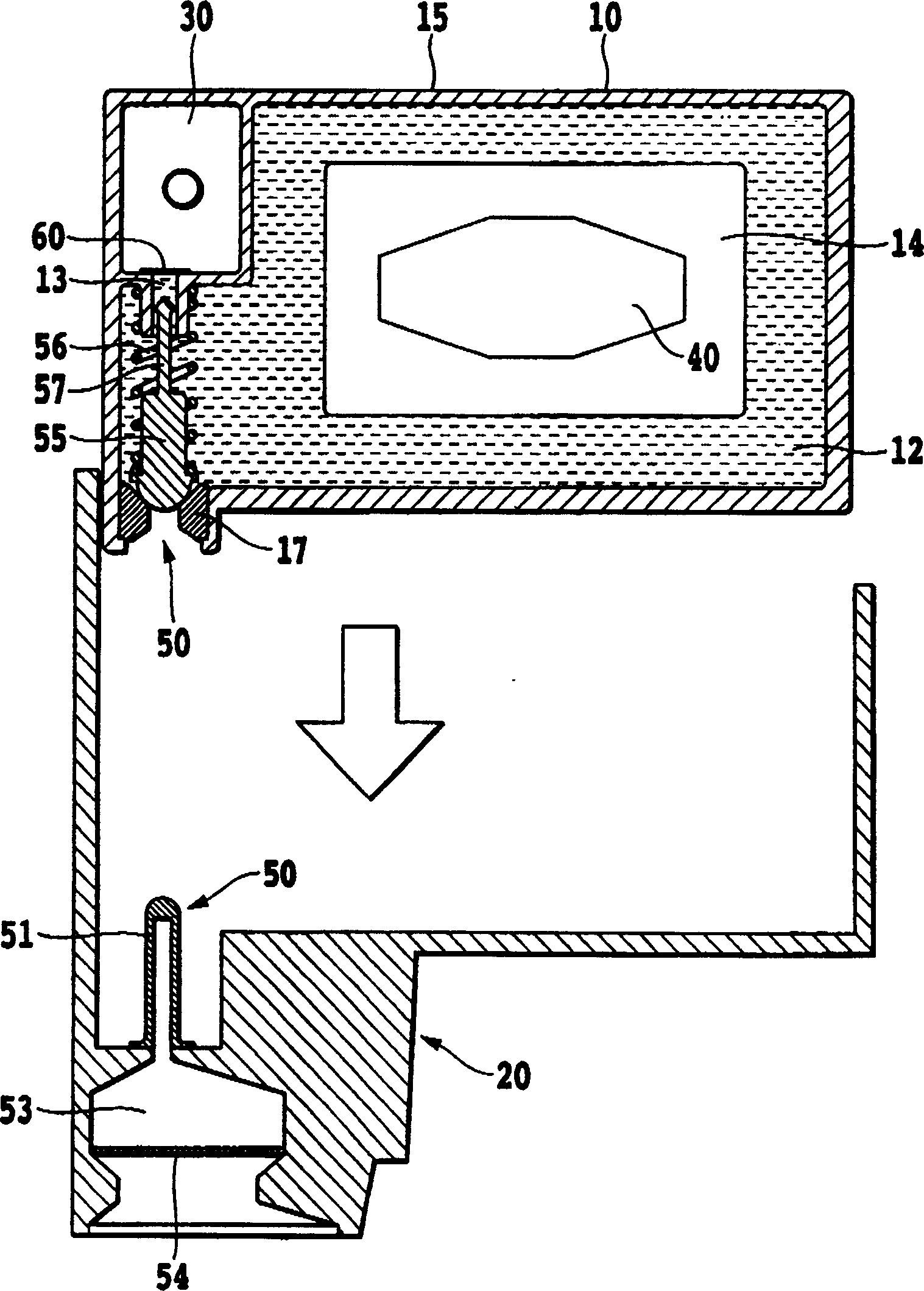
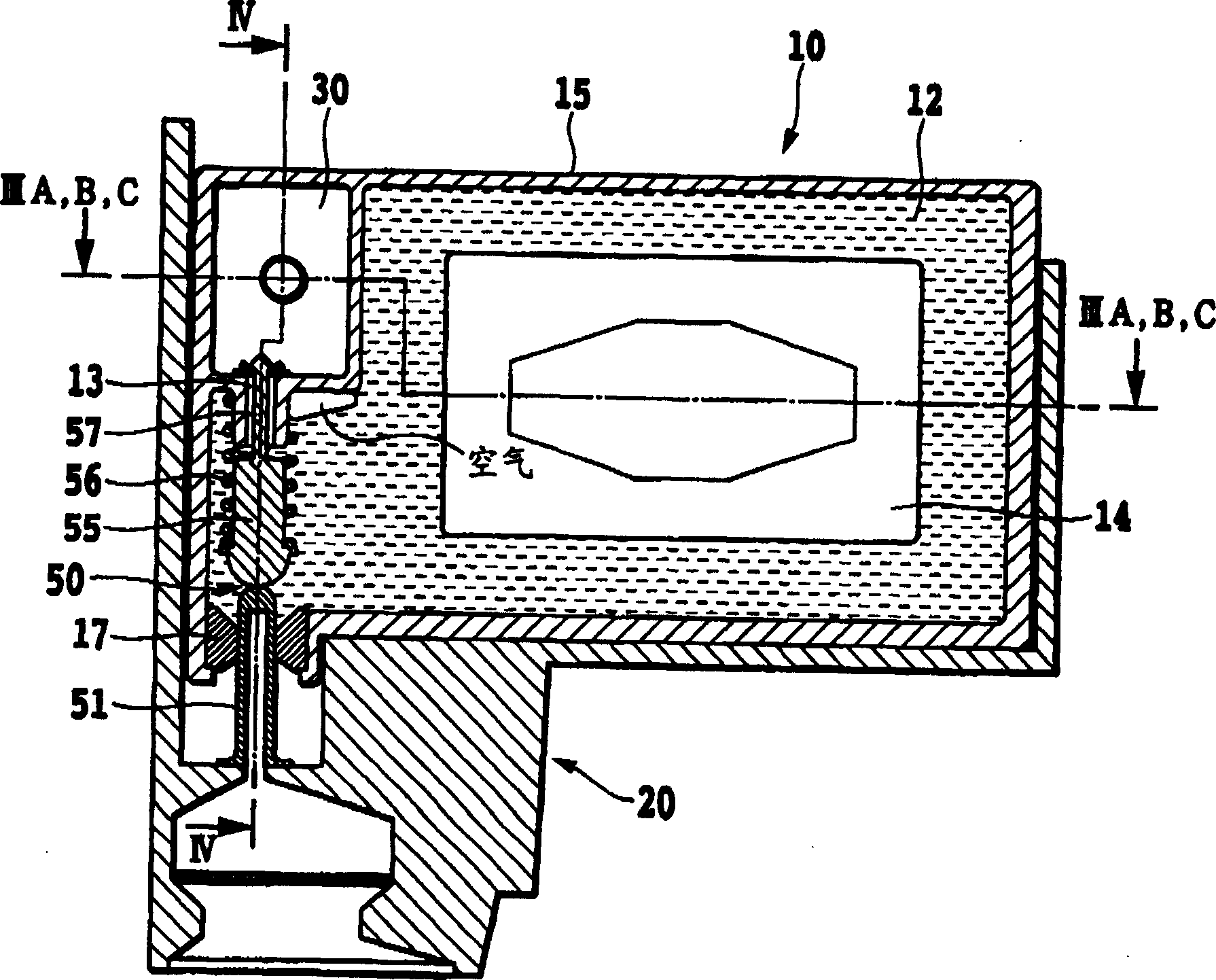
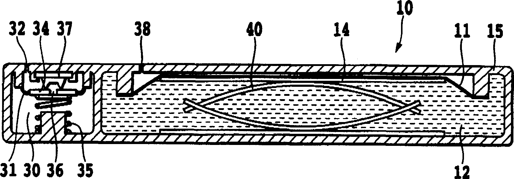
[0077] Figure 1 to Figure 4 It is a figure for demonstrating 1st Embodiment which is a basic structure of this invention.
[0078] figure 1 It is a schematic sectional view for explaining the liquid container and the inkjet recording head according to the first embodiment of the present invention.
[0079] figure 1 The ink supply system of the embodiment shown in , generally, consists of an ink container 10 as a liquid container, an inkjet recording head (hereinafter simply referred to as a 'recording head') 20, and an ink supply path connecting them. The liquid supply unit 50 is configured. The liquid supply unit 50 can be separated or integrated with respect to the recording head 20. In addition, it can also be provided on a carriage (not shown) on which the recording head 20 is mounted. A supply path from the ink container 10 to the recording head 20 is opened at the time.
[0080] The ink container 10 is generally composed of two chambers: an ink storage chamber 12 a...
no. 2 Embodiment approach
[0107] Figure 5 It is a cross-sectional conceptual diagram explaining the second embodiment in the present invention.
[0108] This embodiment differs from the first embodiment in that, firstly, the acicular body 59 formed on the connection closure member 58 is a hollow acicular body and has a communication path 62, and furthermore, the communication path closure member is formed by a narrow slit in the center. The seam rubber 61 of the rubber member is formed. Also in this case, the connection tube 51 constituting the liquid supply part 50 displaces the connection closure member 58 upward in the figure, whereby the ink container 10 and the recording head 20 become in a fluid connection state, and further, the hollow needle-shaped connection closure member 58 The body 59 is inserted into the seamed rubber 61 that closes the valve chamber 30 and the ink storage chamber 12 , and the valve chamber 30 and the ink storage chamber 12 are communicated through the communication path...
no. 3 Embodiment approach
[0112] Figure 6A , 6B It is a sectional conceptual diagram explaining the 3rd embodiment in this invention.
[0113] In this embodiment, as shown in the drawing, the valve chamber 30 is arranged at the center of the ink container 10 , and the communication path 13 connecting the valve chamber 30 and the ink storage chamber 12 is arranged on the side of the valve chamber 30 . In this embodiment, the valve chamber 30 and the ink storage chamber 12 are in a non-communicative state by the diaphragm-shaped check valve 63 shown in the first embodiment. The one-way valve 63, from Figure 6A , 6B It can be understood that it is a structure opened only from the ink storage chamber 12 side to the valve chamber 30 side. Furthermore, on the pressure plate 14 , the needle-shaped body 41 is provided corresponding to the communication path 13 . In addition, the sealing member 17 is made of a rubber material having a slit into which the connection pipe 51 constituting the liquid supply ...
PUM
 Abstract
Description
Claims
Application Information
 - Generate Ideas
- Intellectual Property
- Life Sciences
- Materials
- Tech Scout
- Unparalleled Data Quality
- Higher Quality Content
- 60% Fewer Hallucinations
Browse by: Latest US Patents, China's latest patents, Technical Efficacy Thesaurus, Application Domain, Technology Topic, Popular Technical Reports.
© 2025 PatSnap. All rights reserved.Legal|Privacy policy|Modern Slavery Act Transparency Statement|Sitemap|About US| Contact US: help@patsnap.com


