Eureka AIR delivers breakthrough ideas for toughest innovation challenges, trusted by R&D personnel around the world.

Pressure cavity

A technology of pressure chamber and pressure sensor, which is applied in the direction of pharmaceutical equipment, other medical equipment, dialysis systems, etc., can solve the problem of unstable negative pressure characteristics, achieve stable negative pressure characteristics, improve detection accuracy, and prevent negative pressure characteristics Reduced effect

Active Publication Date: 2014-10-01
ASAHI KASEI MEDICAL CO LTD
View PDF7 Cites 9 Cited by
  • Summary
  • Abstract
  • Description
  • Claims
  • Application Information

AI Technical Summary

Problems solved by technology

[0004] In the case of the conventional pressure chamber, the liquid chamber and the gas chamber are divided by the diaphragm, so it is very effective in that the contact between the liquid and the gas can be effectively blocked, but the verification results of the inventors have shown that for this Such a pressure chamber, the negative pressure characteristics may be unstable

Method used


Image

  • Pressure cavity
  • Pressure cavity
  • Pressure cavity

Examples


no. 1 Embodiment approach )

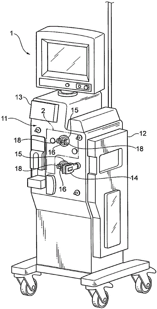
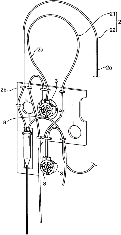
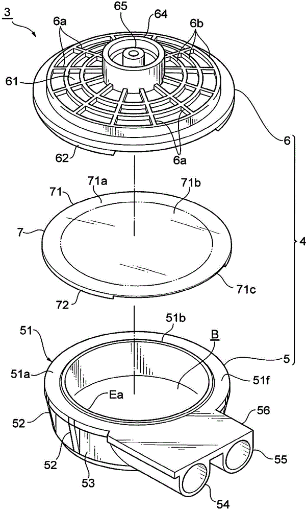
[0045] Next, the pressure chamber 3 of the first embodiment of the present invention will be described. Such as Figure 3 ~ Figure 7 As shown, the pressure chamber 3 has: a container body 4; and a diaphragm 7, which is located in the container body 4, is used to partition the blood chamber B and the air chamber A, and transmit the blood chamber B to the air chamber A through elastic deformation. Pressure.

[0046] The container main body 4 includes a main body casing 5 and a lid casing 6 for blocking the opening of the main body casing 5. In this embodiment, blood Ba is exemplified as a liquid that is required to avoid contact with air, and the main body housing 5 is an example of a liquid chamber container that forms a blood chamber (liquid chamber) B. In addition, the lid housing 6 is an example of a gas chamber container that is coupled to the main body housing 5 to form an air chamber (gas chamber) A communicating with the pressure sensor 1 a.

[0047] The main body housing ...

no. 2 Embodiment approach )

[0087] Next, refer to Picture 11 The pressure chamber 3A of the second embodiment of the present invention will be described. The pressure chamber 3A of the second embodiment has the same members and structure as the pressure chamber 3 of the first embodiment. Therefore, in the following description, the same members and structures are denoted by the same reference numerals as those of the pressure chamber 3 of the first embodiment, and detailed description is omitted, and the description will be centered on the differences.

[0088] Such as Picture 11 As shown, the pressure chamber 3A has: a container body 4A; and a diaphragm 7A in the container body 4A, which separates the air chamber A and the blood supply Ba (refer to Figure 8 ) The flowing blood chamber B is divided, and the internal pressure of the blood chamber B is transferred to the air chamber A through elastic deformation. Furthermore, the container main body 4A includes a main body casing (liquid chamber side conta...


PUM


Abstract

The invention provides a pressure cavity which is disposed in a liquid loop for liquid flowing in case of contacting with air and connected with a pressure sensor which is used for detecting the internal pressure of the liquid loop. The pressure cavity is characterized in that the pressure cavity comprises a liquid cavity container which is provided with a liquid inlet and a liquid outlet and forms a liquid cavity for the flowing of liquid; the pressure cavity also comprises an air cavity container which is combined with the liquid cavity container and forms an air cavity communicated with the pressure sensor; the pressure cavity also comprises a membrane which is clamped by the liquid cavity container and the air cavity container, divides the liquid cavity container and the air cavity container and transfers the internal pressure of the liquid cavity to the air cavity through elastic deformation; a clamping part, used for clamping the membrane, of the liquid cavity container is provided with an inner periphery at a side of the liquid cavity; and an inner side, surrounded by the inner periphery, of the membrane is arranged in a mode of being closer to the air cavity than a virtual interface comprising the inner periphery.

Description

Technical field [0001] The present invention relates to a pressure chamber, which is installed in a liquid circuit such as a blood circuit for supplying blood, blood preparations or supplementary liquid, etc., which requires liquid contact with air to be avoided from flowing, and a pressure chamber for detecting the internal pressure of the liquid circuit. Pressure sensor connection. Background technique [0002] In the case of performing blood purification therapy such as continuous slow blood filtration therapy (CRRT), it is necessary to form a blood circuit for taking blood from a patient, that is, a subject, and performing blood purification on the blood by a blood purification device. After the purification process, the purified blood is returned to the subject. For this blood circuit, from the viewpoint of ensuring sealing performance and ease of use, it is possible to adopt a type that unites the basic structure. For example, a blood circuit is known in which each tube a...

Claims


Application Information

Patent Timeline
Patent Type & Authority Applications(China)
IPC IPC(8): A61M1/16
CPCA61M1/16A61M2205/3331
Inventor 渡边英夫小林贤悟石桥和敏
Owner ASAHI KASEI MEDICAL CO LTD
Why Eureka
Eureka Blog
Learn More