Electronic chronometer
A timepiece and electronic technology, applied to electronic timers, indicating time, time signals, etc., can solve the problems of energy consumption, putting it in a drawer for a few days without looking at it, etc.
- Summary
- Abstract
- Description
- Claims
- Application Information
AI Technical Summary
Problems solved by technology
Method used
Image
Examples
Embodiment Construction
[0028] A detailed description of embodiments of the present invention will be given below with reference to the accompanying drawings.
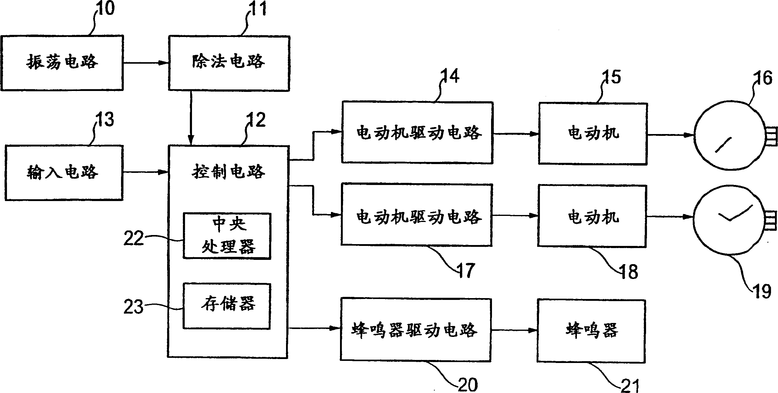
[0029] figure 1 is a block diagram of an electronic timepiece according to an embodiment of the present invention, and is also a block diagram of an electronic timepiece commonly used in each embodiment mentioned below.
[0030] exist figure 1 Among them, the oscillation circuit 10 generates a clock signal of a predetermined frequency (for example, 32768 Hz), and outputs the clock signal to the division circuit 11. The division circuit 11 generates timepiece signals (for example, a 1 Hz second signal for driving the second hand 16 to rotate, a 1 / 5 Hz minute signal for driving the hour / minute hand 19 to rotate) by dividing the frequency of the clock signal, and a clock signal for rapid progress. A 32 Hz rapid feed signal is given to the second hand 16 and the hour / minute hand 19 , and these signals are output to the control circuit 12 .
[...
PUM
 Abstract
Description
Claims
Application Information
 - R&D
- Intellectual Property
- Life Sciences
- Materials
- Tech Scout
- Unparalleled Data Quality
- Higher Quality Content
- 60% Fewer Hallucinations
Browse by: Latest US Patents, China's latest patents, Technical Efficacy Thesaurus, Application Domain, Technology Topic, Popular Technical Reports.
© 2025 PatSnap. All rights reserved.Legal|Privacy policy|Modern Slavery Act Transparency Statement|Sitemap|About US| Contact US: help@patsnap.com


