
Bio-robot waist mechanism

A humanoid robot and waist technology, applied in manipulators, program-controlled manipulators, manufacturing tools, etc., can solve problems such as reducing the stability of humanoid robot motion, limiting the range of motion of humanoid robots, and improving the center of gravity of humanoid robots. The effect of motion and power performance, reduction of power consumption, improvement of compliance and anti-interference ability

Inactive Publication Date: 2006-04-19
SHENYANG INST OF AUTOMATION - CHINESE ACAD OF SCI
View PDF0 Cites 0 Cited by
  • Summary
  • Abstract
  • Description
  • Claims
  • Application Information

AI Technical Summary

Problems solved by technology

[0004] 2) The series drive requires that the motors and transmission chains that drive the two directions of motion are located in two different planes up and down, which increases the height of the waist, increases the center of gravity of the humanoid robot, and reduces the motion stability of the humanoid robot;
[0005] 3) The error of the series drive is the accumulation of the errors of the two joints, which leads to the amplification of the waist error
[0006] In addition, the waist mechanism of the humanoid robot can also adopt a parallel mechanism. The parallel mechanism can arrange the drive motor on a plane, which overcomes the above-mentioned shortcomings of the series mechanism, but the movement range of the parallel mechanism is small, which limits the movement of the humanoid robot. scope

Method used


Image

  • Bio-robot waist mechanism
  • Bio-robot waist mechanism
  • Bio-robot waist mechanism

Examples


Embodiment Construction

[0018] The present invention will be described in detail below in conjunction with the accompanying drawings and embodiments.

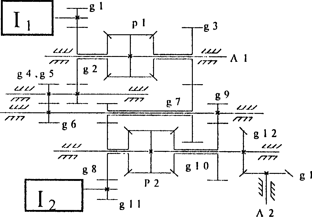
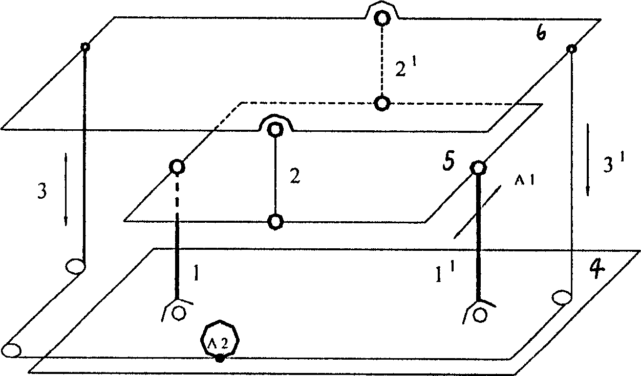
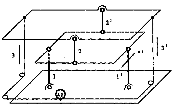
[0019] Such as Figure 1~2 As shown, the present invention is composed of two differential gear train closed transmission mechanisms, upper and lower plates, middle plates, connecting rods, flexible cables, wherein: the two differential gear trains have two degrees of freedom, and the two differential gear trains drive After being closed, it still has two degrees of freedom, and the two differential gear train transmission mechanisms are installed on the lower plate 4, and the first and second connecting rods 1, 1 1 The upper end is fixedly installed on the transverse central axis of the middle plate 5, and the first and second connecting rods 1, 1 1 The lower end is hinged on the transverse central axis of the lower plate 4, the first connecting rod 1 lower end is connected with the first and second motors 1 1 , I 2 Co-driven first output shaft A ...


PUM


Abstract

The presnet invention relates to a robot waist structure. It comprises the two differential pulley system, the up-down board, the middle board, the connecting rod, and soft cable. In the structure the two differential pulley system have to free degrees whether closed or not, and them are installed on the down board. The first and the second connecting rod are fixed on the center axes, the down end of the first connecting rod is connected with the first output axes which is drove by the first and second electromotor, the down end of the second connecting rod is connected with the down board. The third and fourth connecting rod is installed between the middle board and the up board. The first and second soft cable are linked to the center axes of the up board and the second output axes that is driven by the first and second electromotor.

Description

technical field [0001] The invention relates to robot engineering, in particular to a humanoid robot waist mechanism. Background technique [0002] The waist mechanism of traditional humanoid robot often adopts serial drive mode to realize the motion in two directions of pitch and roll. This method has the following disadvantages: [0003] 1) Due to the series drive, the driving motor and transmission chain in one direction become the load of the other motor, which increases the load of the motor; [0004] 2) The series drive requires that the motors and transmission chains that drive the two directions of motion are located in two different planes up and down, which increases the height of the waist, increases the center of gravity of the humanoid robot, and reduces the motion stability of the humanoid robot; [0005] 3) The error of the series drive is the accumulation of the errors of the two joints, resulting in the amplification of the waist error. [0006] In additi...

Claims


Application Information

Patent Timeline
Patent Type & Authority Patents(China)
IPC IPC(8): B25J9/08
Inventor 赵铁军赵明扬王洪光
Owner SHENYANG INST OF AUTOMATION - CHINESE ACAD OF SCI
Learn More