Passenger conveyor

A technology for personnel transportation and equipment, applied in transportation, packaging, escalators, etc., can solve problems such as time-consuming, and achieve the effect of shortening the length

Inactive Publication Date: 2006-04-05
HITACHI LTD +1
View PDF2 Cites 1 Cited by
  • Summary
  • Abstract
  • Description
  • Claims
  • Application Information

AI Technical Summary

Problems solved by technology

In addition, the steps must be removed from the step chains before maintenance and inspection can be performed. Since the operations are carried out in a narrow area, the implementation of these operations will consume a lot of time

Method used


Image

  • Passenger conveyor
  • Passenger conveyor
  • Passenger conveyor

Examples


Embodiment Construction

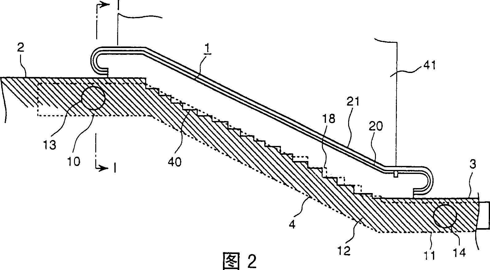
[0016] The following will compare Figures 1 to 5 The escalator shown illustrates a first embodiment of the invention. The escalator 1 essentially consists of a main frame 4 which, as a base frame, bridges the upper floor 2 and the lower floor 3 of the building together. Such as figure 1 As shown, the main frame 4 is composed of side frames 5A and 5B connecting the right side and the left side, a truss (not shown) and a base plate 6 connecting the right side frame 5A and the left side frame 5B together. In addition, the side frames 5A, 5B are composed of an upper truss member 7, a lower truss member 8 and a longitudinal member 9 extending in the longitudinal direction of the escalator, and the longitudinal members are used for the upper truss member 7 and the lower truss member. 8 connections. On the upper floor 2 side of the main frame 4 in the above arrangement is formed an upper horizontal portion 10 , an upper machine room, and on the lower floor 3 side of the main fram...


PUM


Abstract

A passenger conveyor allowing the assembly and the maintenance and inspections of drive machinery and devices to be performed easily and a width dimension to be reduced, wherein the vertical projection of bearings (16) on a drive shaft (15) driving step chains (17) formed of a plurality of steps (18) endlessly connected to each other is overlapped with the tooth parts of drive sprockets (26) and (42) installed on the drive shaft (15) to drive the step chains (17) or fixed to a main frame (4) at a position displaced from the tooth parts to the intermediate part of the drive shaft (15).

Description

technical field [0001] The invention relates to a personnel conveying device, such as an escalator and an electric moving walkway, in particular to a personnel conveying device suitable for being installed in a narrow space. Background technique [0002] In order to reduce the width of the personnel conveying equipment, one of the designs according to the prior art is to directly drive the drive shaft by installing a motor that drives the drive shaft of the steps (for example, Japanese pending patent application 56-108683) , Another design is that the step drive chain is directly driven on the running path (such as Japanese pending patent application 55-40185). [0003] Since the steps and the step chain are directly driven by the motor, the drive chain and the drive sprocket specially used for power transmission can be omitted in the prior art mentioned above. The width can thus be advantageously reduced. [0004] But in the above-mentioned design, driving machines such a...

Claims


Application Information

Patent Timeline
Patent Type & Authority Patents(China)
IPC IPC(8): B66B23/02
CPCB66B23/026B66B23/02
Inventor 小嶋和平齐藤忠一小川博康高桥哲也
Owner HITACHI LTD
Why Eureka
Try Eureka