
Two-stage button switch

A switch and button technology, applied in the field of two-stage button switches, can solve the problems of difficult operation, short pressing stroke, and deterioration of operability, and achieve the effect of easy operation, reduced number of parts, and good operability

Inactive Publication Date: 2006-01-18
ALPS ALPINE CO LTD
View PDF0 Cites 1 Cited by
  • Summary
  • Abstract
  • Description
  • Claims
  • Application Information

AI Technical Summary

Problems solved by technology

[0018] Therefore, when such a two-stage push button switch is used in a digital camera, the pressing stroke at the time of focusing is short, so its operation is difficult and operability deteriorates.
[0019] In a conventional two-stage push button switch, the actuating member 56 is composed of a mounting portion 56a and an actuating portion 56e supported on the mounting portion 56a through a hinge portion 56d, since the actuating portion 56e can move through the hinge portion 56d , so there must be a large space in the horizontal direction, so there is a problem of increasing the structure

Method used


Image

  • Two-stage button switch
  • Two-stage button switch
  • Two-stage button switch

Examples


Embodiment Construction

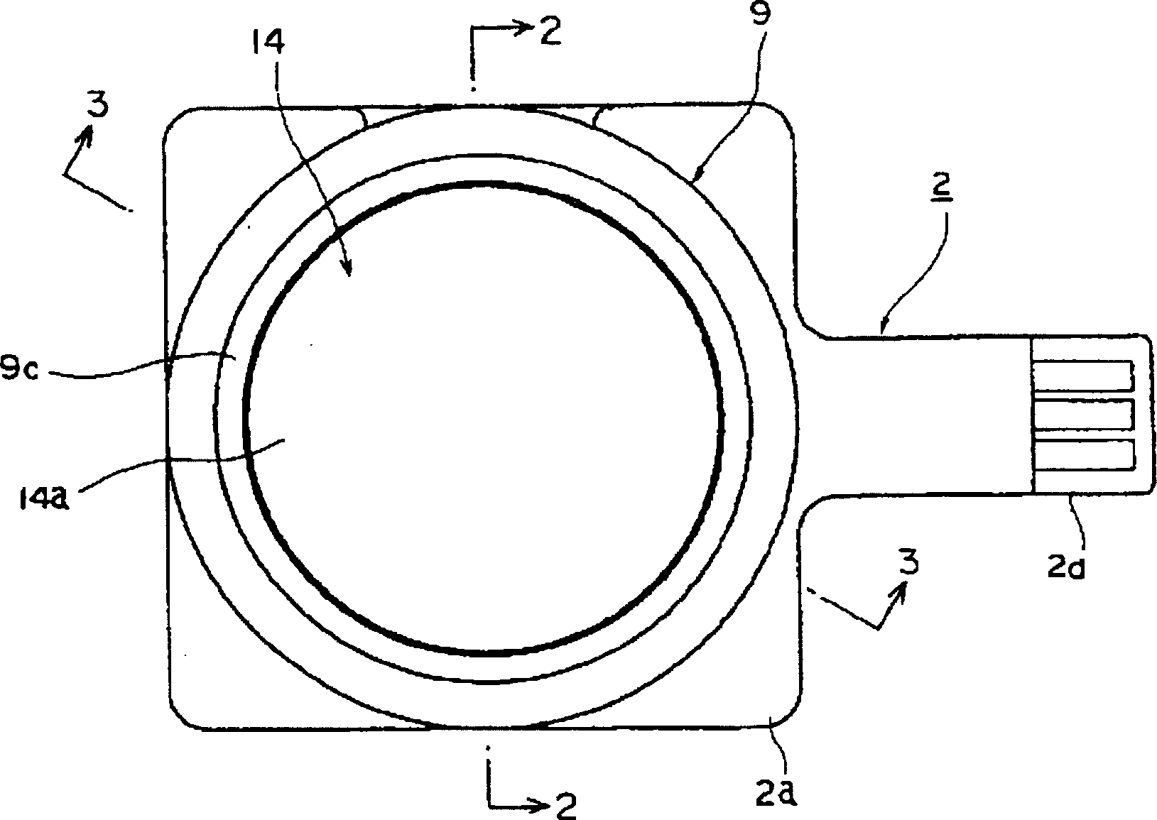
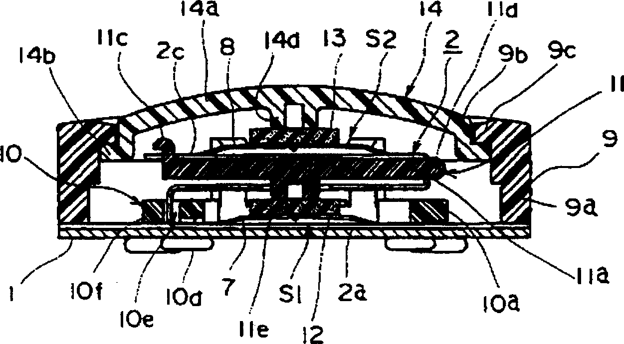
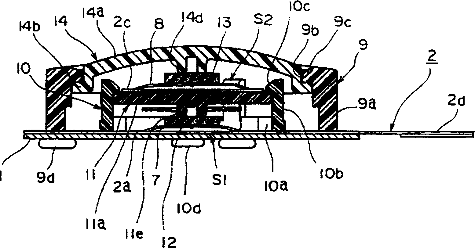
[0093] Below, according to Figure 1-Figure 21 To illustrate the structure of the two-stage push button switch of the present invention. The supporting portion 1 made of metal or the like has four mounting holes 1a provided on the outer side and three mounting holes 1b provided on the inner side. The flexible insulating substrate 2 made of polyester film is especially Figure 5 It has a rectangular base 2a as shown. A strip 2c extends from one side of the base 2a with cutouts 2b on both sides, and a strip 2d extending from one side of the base 2a at a position perpendicular to the strip 2c .

[0094] In addition, the flexible insulating substrate 2 has four mounting holes 2e provided on the outer periphery of the base portion 2a, two mounting holes 2f provided inwardly of the mounting holes 2e, and a circular hole 2g provided on the center of the belt-shaped portion 2c. , A pair of rectangular holes 2h, 2j are provided on the front end of the belt-shaped portion 2c at intervals fr...


PUM


Abstract

The invention provides a pushbutton switch with enhancing the distance of the switch housing of the switch body, and with a good operating performance. In a two-position pushbutton switch, a cushioning member is placed on at least one of first and second click springs, and the click spring is pressed via the cushioning member, thereby making a first press stroke long. A guide member is provided to guide the motion of a driving member. The driving member is slid along the guide member in the pressing direction of a key top.

Description

Technical field [0001] The present invention relates to a two-stage push button switch suitable for digital cameras. Background technique [0002] according to Figure 32-Figure 35 To illustrate the structure of a traditional two-stage push button switch, in the housing 51, the first, second, and third switch bodies S3, S4, and S5 are arranged in the housing 51. The first switch body S3 such as Figure 34 The membrane switch shown is formed by bending a sheet 53 provided with a fixed contact and a movable contact and forming the membrane switch with an insulating sheet 54 provided therebetween. The second switch body S4 is composed of a membrane switch in which a fixed contact provided on the sheet 52 and a movable contact provided on the sheet 53 are opposed to each other through the opening of the insulating sheet 54 to form a membrane switch. [0003] In addition, in the housing 51, a support plate 55 is provided. An actuator 56 is installed on the support plate 55. The actuat...

Claims


Application Information

Patent Timeline
IPC IPC(8): H01H13/64H01H13/14H01H13/52H01H13/807
CPCH01H2233/036H01H2227/028H01H2229/038H01H13/807H01H2203/038H01H13/14H01H13/44H01H2223/054H01H2225/018H01H2229/042H01H2207/004H01H2225/002H01H13/52H01H2215/036H01H2215/004
Inventor 浅井晃佐藤重典大场克一本间幸子
Owner ALPS ALPINE CO LTD
Learn More