
Microwave oven

A technology of microwave ovens and microwaves, which is applied in the field of microwave ovens, and can solve the problems of inability to rotate the cooking tray 4, microwave transmission, and hindering cooking effects, etc.

Inactive Publication Date: 2006-01-11
SAMSUNG ELECTRONICS CO LTD
View PDF0 Cites 0 Cited by
  • Summary
  • Abstract
  • Description
  • Claims
  • Application Information

AI Technical Summary

Problems solved by technology

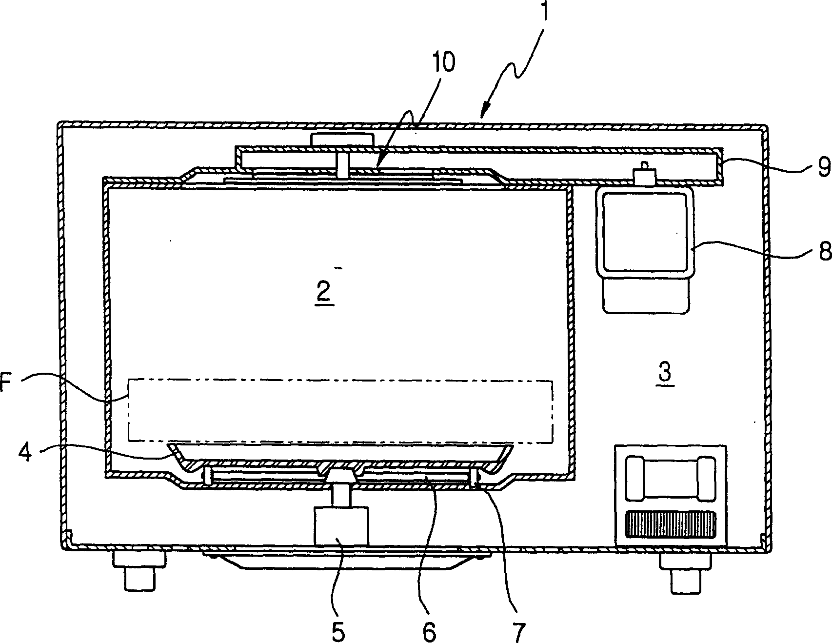
Therefore, microwaves cannot be effectively transmitted to the lower and side portions of the food "F" placed on the cooking tray 4.
[0008] When the size of the food to be cooked is large, the normal operation of the cooking tray 4 may be restricted. In this case, the cooking operation must be carried out, but the cooking tray 4 cannot be rotated.
Thus, the microwaves cannot be directed evenly to the entire portion of the food "F"
Additionally, it is nearly impossible to deliver an effective amount of microwaves to the lower portion of the food "F"
Thus, a microwave oven having such a microwave diffusion unit on the top of the cooking chamber 2 undesirably prolongs the cooking time and prevents the desired cooking effect from being achieved.
[0009] In addition, this arrangement of placing the microwave diffusion unit 10 on the top of the cooking chamber 2 cannot allow the user to see the rotation of the microwave diffusion unit 10 from the outside.
Therefore, the user cannot visually confirm the rotation action of the microwave diffusion unit 10
Correspondingly, the work of a common microwave oven cannot provide the expected good feeling by confirming the rotation of the microwave diffusion unit 10 inside the cooking chamber 2
This hinders the market challenge ability of ordinary microwave ovens

Method used


Image

  • Microwave oven
  • Microwave oven
  • Microwave oven

Examples


Embodiment Construction

[0023] Embodiments of the invention will now be described in detail with reference to examples shown in the accompanying drawings, in which like reference numerals are associated with like parts. The embodiments are described below in order to explain the present invention by referring to the figures.

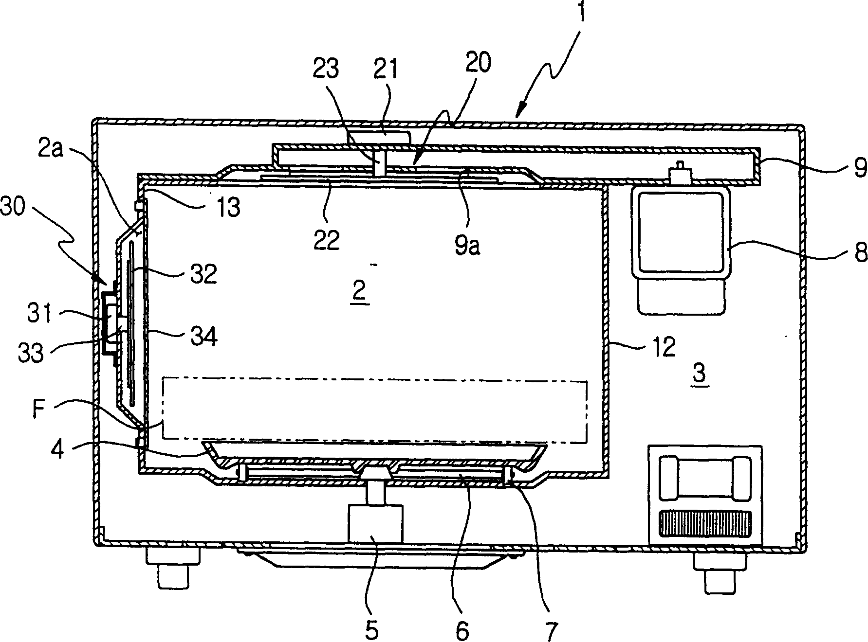
[0024] figure 2 A microwave oven showing an embodiment of the present invention has microwave diffusing units on the ceiling and side walls of its cooking chamber. As shown in the figure, the microwave oven includes an outer casing 1, which constitutes the outer shape of the oven; and a cooking chamber 2 and an equipment chamber 3, which are defined inside the outer casing 1 and separated from each other. The waveguide 9 extends from the upper part of the equipment chamber 3 to the top wall of the cooking chamber 2 . Cooking tray 4 is arranged at the bottom of cooking chamber 2, and food just is placed on it. The cooking tray 4 is rotated at a predetermined speed by a tray ...


PUM


Abstract

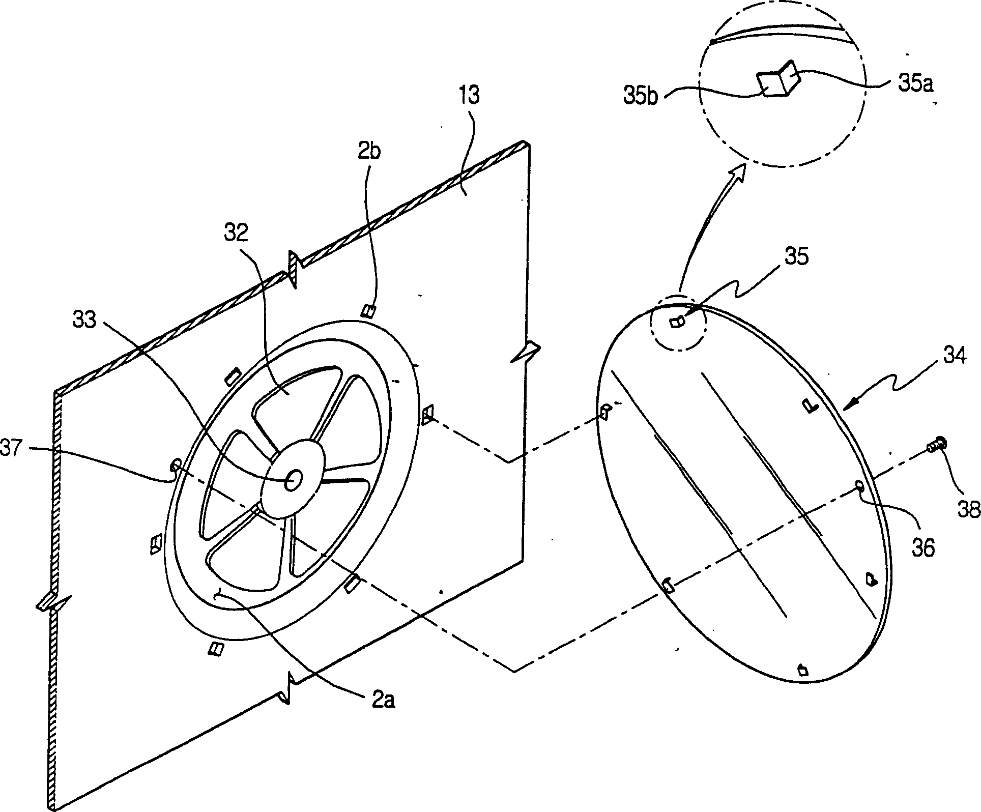
A microwave oven effectively and uniformly cooks large-sized food even though the food inhibits a proper rotation of a cooking tray in a cooking cavity of the microwave oven. An upper wave dispersing unit is provided at a top wall of the cooking cavity and primarily disperses microwaves from the top wall into the cooking cavity. A side wave dispersing unit is provided at a second sidewall of the cooking cavity opposite to a first sidewall of the cooking cavity. The first sidewall partitions the cooking cavity from a machine room of the microwave oven. The side wave dispersing unit secondarily disperses the primarily dispersed microwaves in the cooking cavity. The second sidewall of the cooking cavity has a recess which receives a fan of the side wave dispersing unit. A cover is installed in front of the recess to cover the fan of the side wave dispersing unit. The cover is made of a transparent material and allows a user to view a rotational operation of the side wave dispersing unit.

Description

technical field [0001] The present invention relates to a microwave oven, and in particular, to a microwave oven capable of uniformly cooking food placed on a cooking tray in a cooking chamber of the microwave oven even when the cooking tray is not rotating. Background technique [0002] Generally speaking, a microwave oven is an electrically driven oven that uses high-frequency electromagnetic waves to heat and / or cook food contained in its cooking chamber. The high-frequency electromagnetic waves are generated by the oscillation of a magnetron placed in the equipment compartment of the microwave oven. That is, during a cooking operation, the magnetron installed in the equipment chamber radiates the high-frequency electromagnetic waves (microwaves), passing through the cooking chamber. These microwaves pass through the food, repeatedly changing the arrangement of the moisture molecules contained in the food, causing the moisture molecules to vibrate, generating frictional ...

Claims


Application Information

Patent Timeline
Patent Type & Authority Patents(China)
IPC IPC(8): F24C7/02H05B6/74H05B6/80
CPCH05B6/6426H05B6/74F24C7/02
Inventor 金善基
Owner SAMSUNG ELECTRONICS CO LTD
Learn More