Fixing piece for a windscreen wiper

A technology for fixing parts and wipers, which is used in vehicle cleaning, vehicle maintenance, transportation and packaging, etc., can solve problems such as contact corrosion in the connection area, and achieve the effect of eliminating contact corrosion and reducing manufacturing time and cost.

Inactive Publication Date: 2005-05-18
ROBERT BOSCH GMBH
View PDF0 Cites 0 Cited by
  • Summary
  • Abstract
  • Description
  • Claims
  • Application Information

AI Technical Summary

Problems solved by technology

However, the connection of dissimilar materials presents the risk of galvanic corrosion in the connection area

Method used


Image

  • Fixing piece for a windscreen wiper
  • Fixing piece for a windscreen wiper
  • Fixing piece for a windscreen wiper

Examples


Embodiment Construction

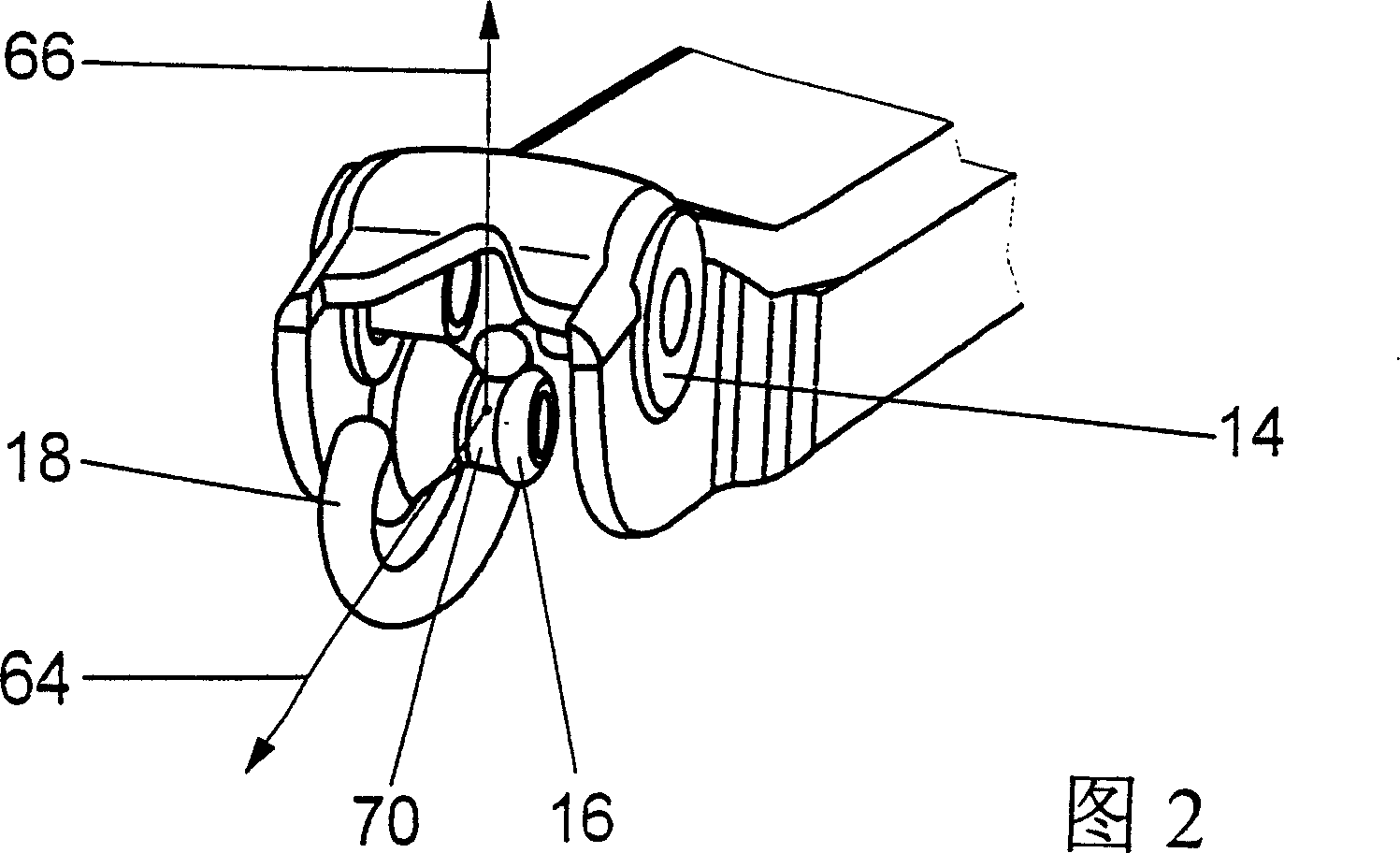
[0022] The fastening part 10 for the windshield wiper has at its one end a receiving opening 12 or 46 ( FIG. 10 ) for receiving the wiper shaft 44 and at its other end forms a component 14 of the folding hinge ( FIG. 1 ). Furthermore, the fastening part 10 has at this end a shaped spring suspension 16 on which a C-shaped hook 18 of a tension spring (not shown) engages. The spring suspension 16 is formed by deep drawing from the side walls 24 of the U-shaped cross-sectional profile 20 ( FIGS. 2 and 9 ).

[0023] Via the C-shaped hook 18, considerable tensile forces 64 and 66 act on the spring suspension 16 from different directions. The cross-section of the spring suspension 16 has a circular hollow profile, which has a maximum cross-section in the transition region to the side wall 24 until it is reduced to a constriction 34, whereby the cross-section of the spring suspension 16 The section is correspondingly solidly constructed. The constriction 34 forms the engagement regi...


PUM


Abstract

The invention relates to a mounting (10) for a windshield wiper, the mounting having at one end a receiving hole (12, 46) for a wiper shaft (44), forming a fold at the other end A component (14) of the hinge, and formed by deep drawing, stamping and bending from a flat plate (28), has a U-shaped cross-sectional profile (20) and a spring suspension (16). It is proposed that the spring suspension (16) is formed from a side wall (24) of the U-shaped cross-sectional profile (20) by deep drawing.

Description

technical field [0001] The invention relates to a mounting for a windshield wiper. Background technique [0002] The known windshield wiper has a wiper arm consisting of a driven fastening part and an articulation part with a wiper lever connected to it by a folding hinge. A wiper blade is hinged to the free end of the wiper rod. During the swivel movement of the windshield wiper blade, the wiper blade moves over the vehicle windshield, a tension spring tensioning the folding hinge so that the wiper blade is pulled towards the windshield. [0003] The tension spring is housed in the U-shaped cross-sectional profile of the hinge and is suspended at one end from a transverse pin of the hinge. The other end of the tension spring is fixed on the spring suspension device on the fixture by a C-shaped hook. In known fastening elements, the spring suspension is either formed on or consists of a rivet. For example, in a variant, the fixing part, which is formed as a plate bend, h...

Claims


Application Information

Patent Timeline
Patent Type & Authority Patents(China)
IPC IPC(8): B60S1/34
CPCB60S1/3438B60S1/3459B60S1/3468Y10T29/49622B60S1/34
Inventor 约阿希姆·齐默尔
Owner ROBERT BOSCH GMBH
Why Eureka
Try Eureka