
Flying negative pressure air bearing slider with divided negative pressure pockets

A slider, air technology, applied in the hydrodynamic spacing of the head, instruments, support heads, etc., can solve problems such as adverse performance and influence, and achieve the effect of small actual contact area, constant suspended gram load, and stable floating state

Inactive Publication Date: 2004-10-27
SAMSUNG ELECTRONICS CO LTD
View PDF0 Cites 0 Cited by
  • Summary
  • Abstract
  • Description
  • Claims
  • Application Information

AI Technical Summary

Problems solved by technology

These buildups can eventually adversely affect performance as the accumulated particles can cause head crashes and excessive wear of the heads and platters

Method used


Image

  • Flying negative pressure air bearing slider with divided negative pressure pockets
  • Flying negative pressure air bearing slider with divided negative pressure pockets
  • Flying negative pressure air bearing slider with divided negative pressure pockets

Examples


Embodiment Construction

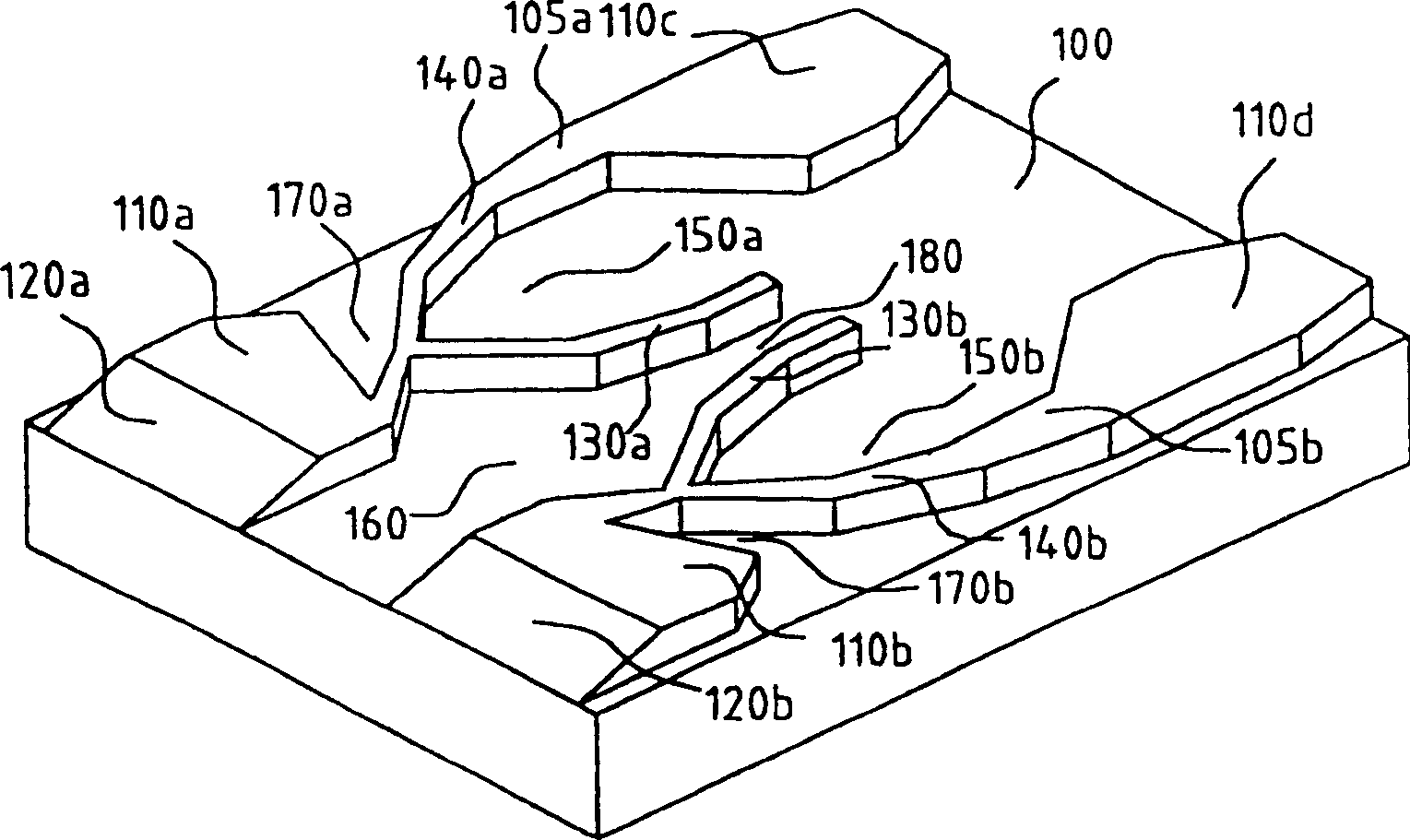
[0036] The present invention generally relates to floating air bearing sliders with spaced negative pressure pockets or cavities. image 3 is a bottom perspective view of the improved floating NPAB slider of the present invention, Figure 4 A bottom plan view of the modified slider embodiment is shown.

[0037] The following discussion is conditioned on the floating air bearing slider body 100 floating above the surface of the recording disk during the relative rotation of the recording disk. The slider body 100 has a main surface facing the magnetic disk surface, and on the main surface, rail and groove patterns are formed. The major surface has a leading edge (front), a trailing edge (rear), a first side and a second side, wherein the leading edge is upstream of the trailing edge spaced relative to the longitudinal axis of the slider body, the longitudinal direction Corresponds to the tangential rotation direction of the recording disk. The first side is spaced apart from...


PUM


Abstract

A flying NPAB head slider configured for supporting a transducer proximate to a rotating disc. The slider includes two side rails extending from the leading edge to the trailing edge of the slider body, which form air bearing surfaces that develop positive lifting forces as the disc rotates beneath the slider. Two negative pressure air cavities are created, one proximate to each of the side rails in a central portion of the slider body, separated from each other by curved cross rails. In addition, two more negative pressure air cavities are created forward of the central negative pressure air cavities. The central and forward negative pressure air cavities on each side of the slider are divided by narrow central air bearing rails segments, which safely maintain the stable trapped drawing or suction forces in the cavities regardless of large skew angle variations while the disc drive is operating.

Description

technical field [0001] The present invention relates to magnetic recording devices. In particular, the present invention relates to flying slider heads having magnetic transducers for writing data to and reading data from a recording medium such as a magnetic disk. Background technique [0002] Magnetic recording systems transfer data through a transducer supported by an air-supporting film or layer as the transducer moves relative to the disk surface. The transducer needs to "float" just a few microinches above the surface of the spinning disk (flying head), or touch the spinning disk slightly within a safe range (pseudo-contact head). [0003] An air-supported film is created by pressurized air as air flows between the rotating disk surface and the slider body. For flying heads, the air bearing acts to provide an extremely thin gap between the slider body and the spinning disk without physical contact. This will minimize surface wear and damage to the flying head and di...

Claims


Application Information

Patent Timeline
Patent Type & Authority Patents(China)
IPC IPC(8): G11B5/60G11B21/21
CPCG11B5/6005G11B21/21
Inventor 朴基旭张东燮郑仁燮朴太锡
Owner SAMSUNG ELECTRONICS CO LTD
Learn More