
Method and device for cutting to length strips or sheets in rolling or transport line

A technology of transverse cutting and rolling line, which is applied in the direction of shearing and forming blank devices, shearing devices, knives for shearing machine devices, etc., and can solve problems affecting the operation of the strip

Inactive Publication Date: 2004-09-29
SMS SCHLOEMANN SIEMAG AG
View PDF2 Cites 0 Cited by
  • Summary
  • Abstract
  • Description
  • Claims
  • Application Information

AI Technical Summary

Problems solved by technology

In conclusion, due to the non-movable setting of the shears in the area of ​​the rolling line or conveyor line, the access to the range of the roller table may be seriously affected, and sometimes the strip running

Method used


Image

  • Method and device for cutting to length strips or sheets in rolling or transport line
  • Method and device for cutting to length strips or sheets in rolling or transport line
  • Method and device for cutting to length strips or sheets in rolling or transport line

Examples


Embodiment Construction

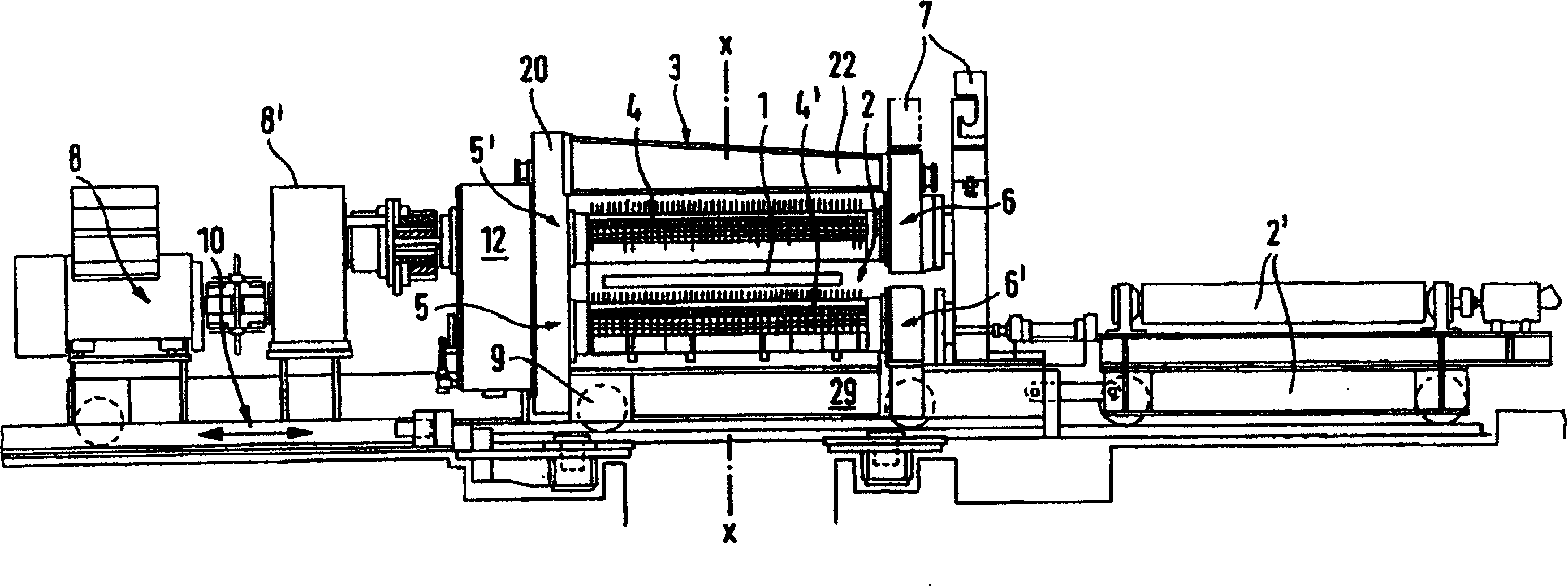
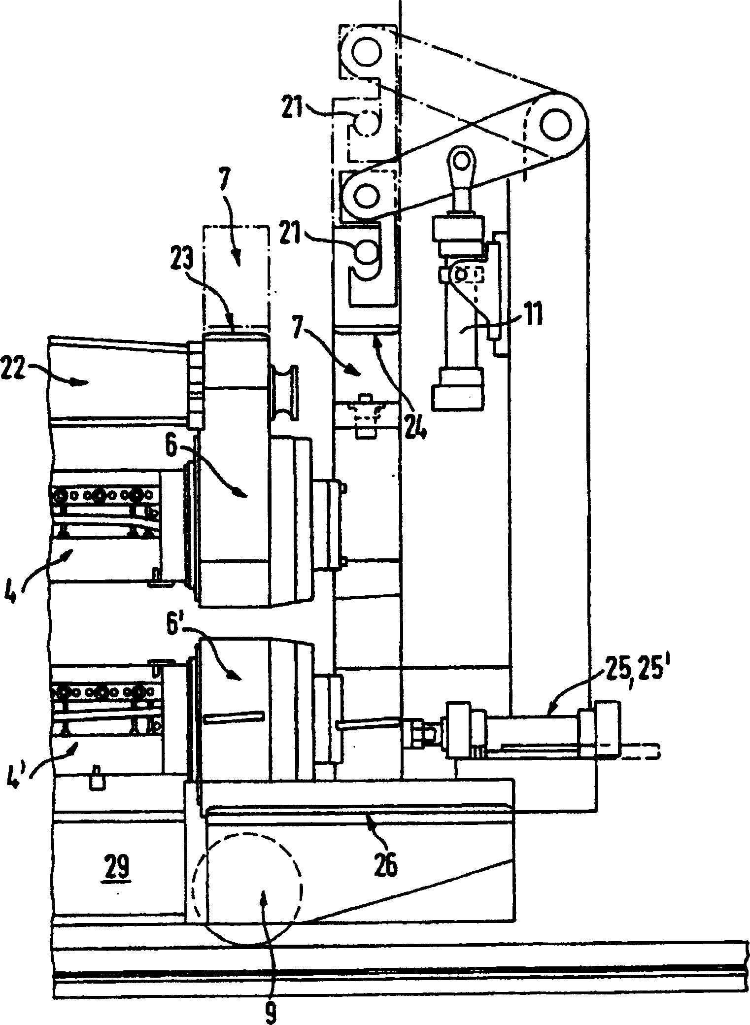
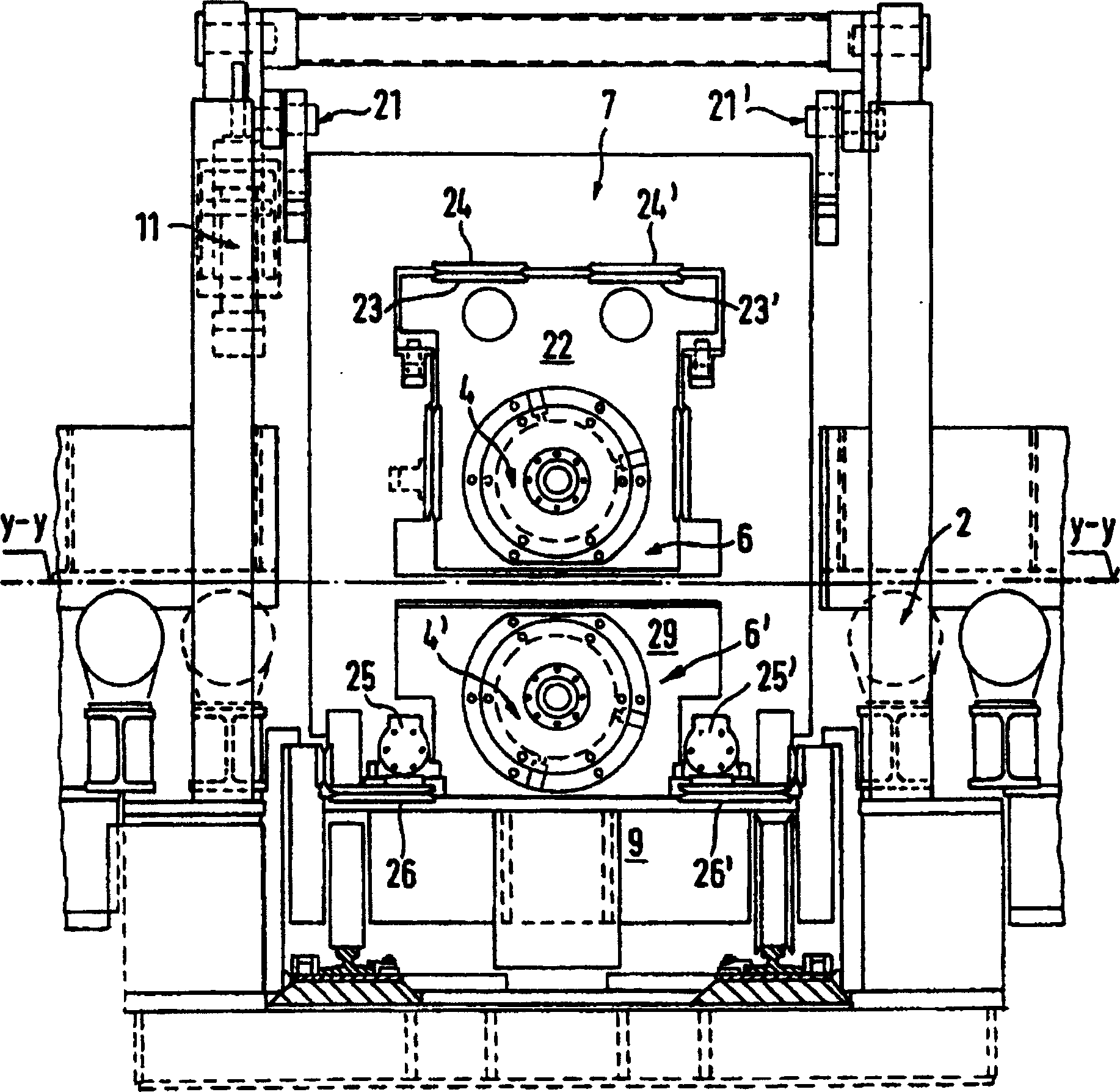
[0026] figure 1 The device shown is used for transverse cutting of plate strip 1 on rolling line or conveying line x-x, particularly on roller table 2, wherein shearer 3 is in a position about to cut, it has still The cantilevers 22, 29 of its frame 20 in the open state. The shearing machine has a drive 8 with a reduction gear 8 ′ and a synchronous drive 12 fastened to a frame 20 . The shearer with its drive is moved perpendicular to the rolling line or conveying line x-x via a travel drive 10 and a carriage 9 guided by rails. Said trolley frame 9 is connected to a movable part 2' of said roller table 2 and moves together with the shearer 3 in such a way that when the shearer 3 is as figure 1 When shown outside the roll line x-x, move into the roll line x-x, and vice versa, re-enter the roller table 2 when the shearer 3 moves out.

[0027] Such as figure 1 As shown, at least one clamping part 7 with actuating means 11 , 25 , 30 , 36 is arranged at the roller table-side end...


PUM


Abstract

The invention relates to a method and a device for cutting to length strips (1) or sheets in the rolling or transport line (x-x), notably on a rolling table (2), using shears (3) having one blade holder (4, 4') each arranged above and below the strip (1), which blade holders are guided by means of fixing elements (5, 5'; 6, 6'). The invention is characterized in that the shears (3) with the blade holders (4, 4') and their fixing elements (5, 5'; 6, 6') are displaced sideward out of the rolling line (x-x) into a neutral parking position after each cut when a strip or sheet is located in the rolling or transport line. Before displacement of the shears (3) the frontal joint between the blade holders (4, 4') or between the fixing elements (6, 6') overlapping the rolling line (x-x) is opened. For a subsequent cut the shears are moved into the rolling line such that they overlap same in a U-shape. Before the next cut the frontal joint between the blade holders (4, 4') or between the fixing elements (6, 6') overlapping the rolling line (x-x) is closed. Said joint is coupled in a positive and non-positive manner by means of a clamping element (7).

Description

technical field [0001] The present invention relates to a method for replacing a shear when cutting plate strip transversely on a rolling line or conveying line with a roller table, the shear having separate knife holders above and below the strip and the shear is guided by the gripper. The invention also relates to a device for carrying out the method. Background technique [0002] Known stationary shears or mobile cutting shears can be moved in and out of the rolling line or the roller table, provided that the roller table is free of the strip to be cut within the range of the shears or another cutting device. [0003] A shear permanently attached to a roll or conveyor line is mostly considered obstructive since it covers an area of ​​the roller table where it is difficult to control. Shears located on the rolling line or on the conveyor line can also affect the running of the strip as the strip ends pass through. The shear also constitutes an interfering factor in the ...

Claims


Application Information

Patent Timeline
Patent Type & Authority Patents(China)
IPC IPC(8): B23D15/08B21B15/00B23D1/00B23D19/00B23D25/02B23D25/12B23D35/00
CPCY10T83/8742Y10T83/483Y10T83/8748B23D25/12B23D35/008Y10T83/8743B21B2015/0014B23D35/00
Inventor H·格拉菲B·拉达-尊克M·明克尔
Owner SMS SCHLOEMANN SIEMAG AG
Learn More