
Sensing head drive

A sensing head and drive technology, which is applied to the configuration/installation of instruments and heads, recording/reproduction by optical methods, etc., can solve the problems of increased manufacturing cost and complicated manufacturing process of optical sensing head devices, and achieve simplified manufacturing Process, the effect of reducing manufacturing costs

Inactive Publication Date: 2004-06-30
SAMSUNG ELECTRONICS CO LTD
View PDF0 Cites 0 Cited by
  • Summary
  • Abstract
  • Description
  • Claims
  • Application Information

AI Technical Summary

Problems solved by technology

Therefore, the manufacturing process of the optical pickup device becomes more complicated, and its manufacturing cost increases accordingly

Method used


Image

  • Sensing head drive
  • Sensing head drive
  • Sensing head drive

Examples


Embodiment Construction

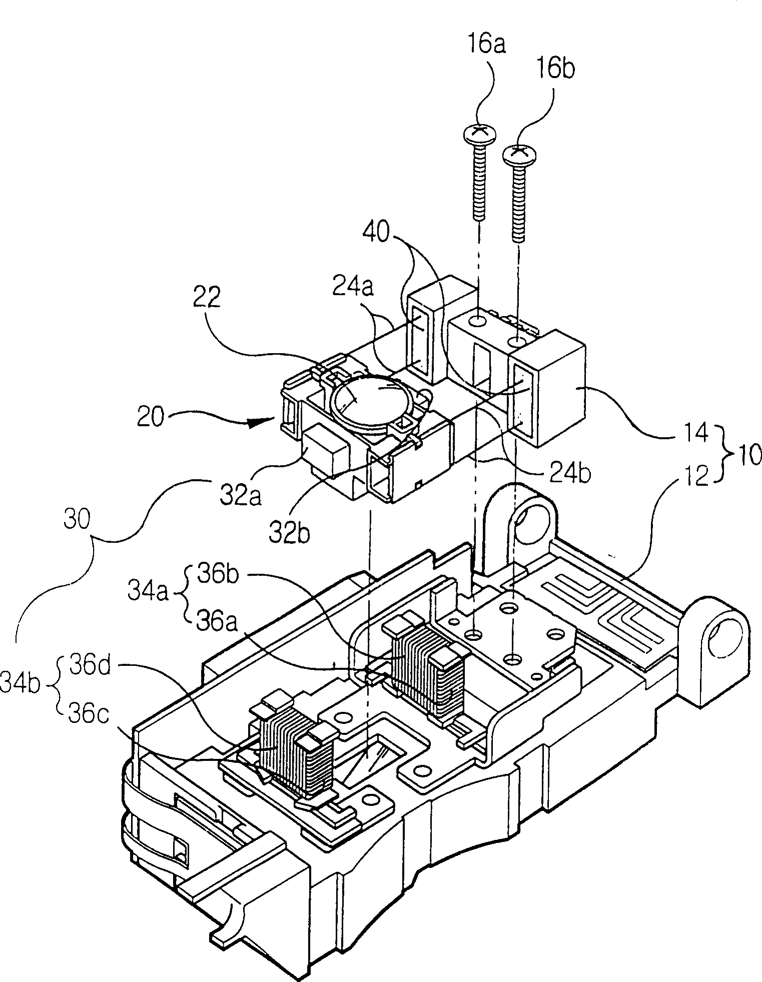
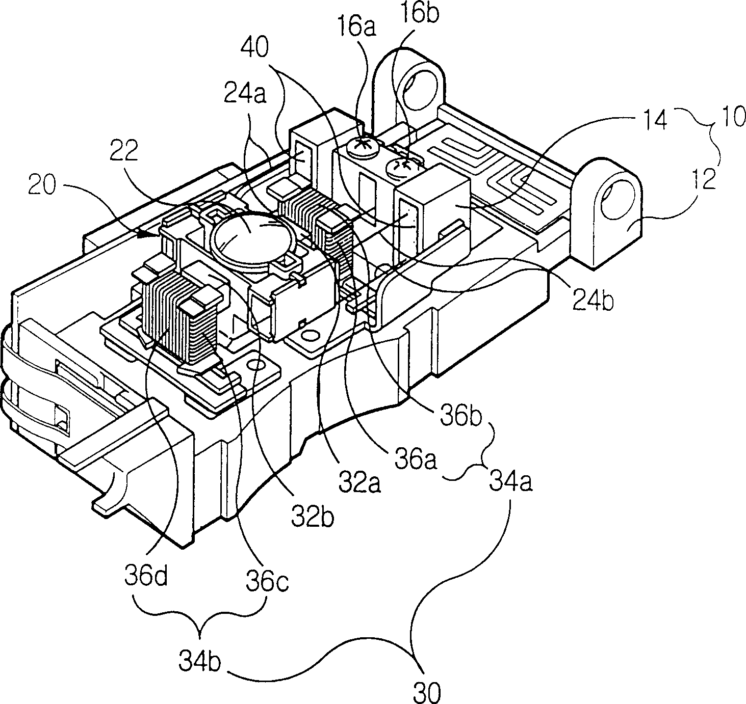
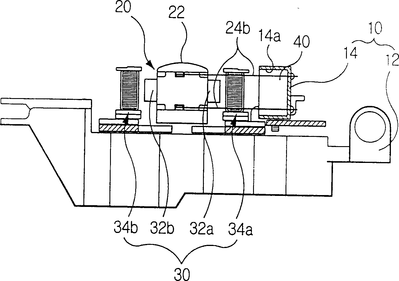
[0060] Figure 5A to Figure 6 Shows the sensor head driver according to the first preferred embodiment of the present invention. It will be found that the marking numbers on the same components are also the same. Correspondingly, the reference numeral 10 in these figures denotes a base member, 20 denotes a lens holder, 30 denotes a lens holder driving device, and 50 denotes a damping fluid.

[0061] Such as Figure 5A to Figure 6 As shown, the base member 10 includes a body portion 12 and a holder support portion 14. The holder supporting part 14 is fixed to the upper part of the body part 12 by a pair of screws 16a and 16b.

[0062] An objective lens 22 is mounted on the lens holder 20. The lens holder 20 is suspended on the holder supporting portion 14 of the base member 10 by two pairs of wire springs 24a and 24b, and can move in the focusing direction and the tracking direction at the same time.

[0063] The lens holder driving device 30 includes a pair of magnets 32a and 32b...


PUM

PropertyMeasurementUnit
Viscosityaaaaaaaaaa

Abstract

A pickup actuator having a base member as a fixed member, a lens holder as a travelling member, wherein a damping fluid is applied therebetween. The damping fluid damps a vibration occurring at the lens holder when the lens holder is driven. Here, the damping fluid has a viscosity ranging from 1000cP to 2000cP at 27 DEG C, in which magnetic particulates are stably dispersed. It is preferable that the damping fluid is magnetized to 100G SIMILAR 200G in a magnetic field of 3 SIMILAR 4k0e. When there occurs vibration at the lens holder by any reasons, such vibration is directly damped by the damping fluid applied between the base member and the lens holder.

Description

Technical field [0001] The present invention relates to a sensor head driver used in an optical device for recording information on or reproducing information from an optical disc by an optical method. Background technique [0002] As an emerging technology in the current era, the field of optical technology for recording / reproducing information on / from an information recording carrier such as an optical disc has become a hot research topic. In particular, the sensor head driver is regarded as an important component in the optical device because it determines the speed of information recording / reproduction. This sensor head driver mainly includes a base part, a lens holder, and a lens holder driving device. The lens holder is movably arranged relative to the base member. An objective lens is mounted on the lens holder. The objective lens projects a light beam to the recordable side of the optical disc to read optical signals or record information on the optical disc. The lens hol...

Claims


Application Information

Patent Timeline
IPC IPC(8): G11B7/09
CPCG11B7/0933G11B7/0932G11B7/0935
Inventor 申景湜
Owner SAMSUNG ELECTRONICS CO LTD
Learn More